


Fertilizer leaking out of a storage tank is not just a safety hazard, it is also an expensive problem. This makes selecting a fertilizer storage tank so important, whether you’re a fertilizer dealer handling bulk storage or a farmer looking for on-farm solutions, the right material, size, and shape counts.
For decades, Dultmeier Sales has been helping fertilizer retailers and farmers with fertilizer storage and this has gained us valuable insights. In this post, we’ll use this knowledge to cover the different types of liquid fertilizer storage tanks—polyethylene, fiberglass, steel, and stainless steel—and the pros and cons of each. We’ll also go over the different sizes and shapes, examining which ones work best for what.
Selecting a Liquid Fertilizer Storage Tank
No matter what type of fertilizer there are two crucial things to consider up front. First is the compatibility of the fertilizer with the tank material. Second is the weight of the fertilizer.
1. Compatibility of Fertilizer with Tank Material
Different fertilizers have varying properties that can interact differently with different tank materials. For instance, some micronutrient formulations can have pH levels (extremely low or high), which may not be compatible with certain tank materials.
See also: Chemical Compatibility Charts
2. Weight of the Fertilizer
Liquid fertilizers are denser than water, and their weight can vary depending on their composition. For example, Urea Ammonium Nitrate (UAN) solutions can have densities up to around 11 pounds per gallon. It’s crucial to ensure that the selected tank can support the weight of the fertilizer, especially when dealing with large volumes.
By carefully considering both the chemical compatibility and the weight of the fertilizer, you can select a storage tank that ensures safety and longevity in your fertilizer storage solutions.
Other Factors to Consider
Beyond fertilizer compatibility and weight, there are several other key factors to consider when selecting a liquid fertilizer storage tank:
- Tank Location & Installation: ensure that tank outlets and tie-downs are not interfering with other tanks, pipes, etc.
- Venting & Pressure Management: Proper venting aids filling and unloading
- Mixing & Agitation: Suspension fertilizers may settle, requiring built-in agitation
- Filling & Dispensing: Ensure easy loading/unloading for nurse trailers or sprayers.
- Regulatory Compliance: Ensure you are aware of all guidelines you may be subject to
- Future Expansion: Tank layout and location should make any expansion simple to add (if possible).
Best Storage Tank Options for Liquid Fertilizer
Tank material is the primary attribute that separates different tank options. Material affects the lifespan, cost, compatibility, repairability, installation, temperature rating, and more.
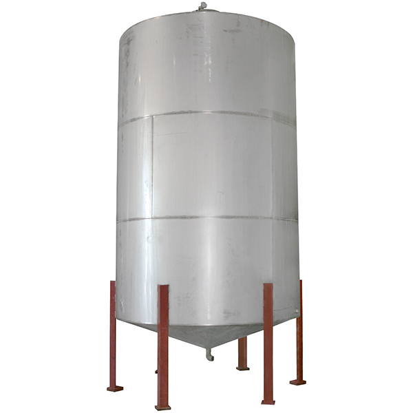
Steel Tanks
Steel tanks are often used to store large quantities of fertilizer. They are typically made to order and typically used to store large volumes, 30,000 gallons or more. Their durability makes them a reliable choice, however, there are some drawbacks. Here are the keys to consider:
Advantages of Steel Tanks for Fertilizer
- Durability & Strength – Steel tanks are highly durable and can withstand physical impacts better than plastic or fiberglass.
- Long Lifespan – With proper maintenance, steel tanks can last 20+ years, making them a solid long-term investment.
- Fire Resistance - Steel does not melt and is not going to warp under higher temps.
- High Capacity Options – Steel tanks can be custom-built in large sizes (30,000+ gallons), making them ideal for bulk fertilizer storage.
- Repairable - Steel can be welded, patched, and painted as needed.
- Resale Value – Steel tanks hold some resale value and can be scrapped or repurposed if no longer needed.
Disadvantages of Steel Tanks for Fertilizer
- Corrosion Risk – Steel is prone to rust and corrosion, especially with certain fertilizers (UAN solutions, ammonium nitrate). Requires protective coatings or linings to prevent deterioration.
- Higher Cost – Initial purchase and installation costs are typically higher compared to polyethylene or fiberglass tanks.
- Upkeep – Welded seams and fittings can develop leaks over time, requiring maintenance and inspection.
- Compatibility – Some highly corrosive fertilizers may still degrade lined steel tanks over time.
- Lead time - Steel tanks are typically made to order and not readily available due to the potential custom nature of each order.
Steel tanks can be equipped with several fittings and features at the factory including sight gauges, vents, manways, lift lugs, fill/outlet fittings, etc. Contact us to get a quote and shipping estimate on a steel storage tanks.
Steel Tanks Manufactured by:
Fiberglass Tanks

Storing fertilizer in fiberglass tanks is a very practical choice. They are available in sizes ranging from about 8000 gallons up to 30,000 gallons. Typically, these tanks have a 12 ft diameter and a height ranging from 10 - 35 ft.
Advantages of Fiberglass Tanks for Fertilizer
- Corrosion Resistance - Excellent resistance to corrosion, suitable for a wide range of chemicals. Special resins available to handle certain chemicals and fertilizers.
- Lightweight - Easier to handle and install compared to steel tanks.
- Lifespan – Can last longer than steel if properly maintained. UV coatings can be reapplied to increase lifespan.
- Durability - Long lifespan with proper maintenance.
Disadvantages of Fiberglass for Fertilizer
- Cost - Generally more expensive than polyethylene tanks.
- Susceptibility to Damage - Can be prone to impact damage if not handled carefully. Prone to puncture or cracks if impacted by equipment.
- Difficult to Repair - Fixing damage will require specialized training
- Availability - Like steel, tanks are custom made to order and not readily available
Fiberglass tanks are also made to your specs at the factory ensuring they fit your location and can handle the liquid to be stored. Available options include: sight gauges, lift lugs, vents, manways, flanged outlets, re-circulation packages, etc. Call us for a quote on a fiberglass fertilizer storage tank.
Fiberglass Tanks Manufactured by:
Polyethylene Tanks
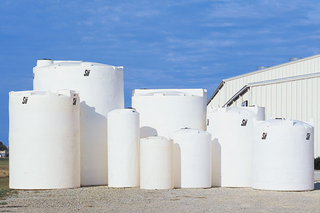
Polyethylene or “poly” tanks are a versatile option for fertilizer storage. They come in the widest range of sizes and shapes to suit a wide range of needs. Typically used for sprayer, nurse trailers, tender trailers, and cone bottom inductor tanks, poly tanks are also used for bulk liquid fertilizer storage.
Polyethylene has excellent compatibility with a wide variety of fertilizers, and although they are not as durable as steel or stainless, they can be made to store heavy liquids (14lbs/gal or more if needed) such as 10-34-0. Be sure to confirm that a tank has a Specific Gravity rating that will handle the fertilizer you want to house.
Advantages of Poly Tanks with Fertilizer
- Corrosion Resistance - Highly resistant to a variety of chemicals, making them suitable for storing fertilizers.
- Lightweight - Easier to transport and install due to their reduced weight.
- Cost-Effective - Generally more affordable compared to other materials.
- Availability - Poly tanks are made in standard sizes and can be found in stock. (Dultmeier keeps several tank sizes in stock, we can get tanks that are not in stock, typically in 4-12 weeks depending on the tank)
Disadvantages of Poly Tanks with Fertilizer
- Temperature Sensitivity - Can become brittle in extremely cold temperatures and may deform under high heat.
- Limited Lifespan - Typically have a shorter lifespan compared to steel or fiberglass tanks.
- Limited Size - The manufacturing process of poly tanks is limited in size, typically 20,000 gallons is the largest poly tank that is available.
At Dultmeier Sales we offer a variety of polyethylene tanks suitable for fertilizer storage supplied from Ace Roto Mold, Snyder, and Norwesco. Poly tanks can be custom built but typically, the tanks are made in standard configurations and more readily available.
You can contact us to find the available poly tank options that are able to store fertilizers.
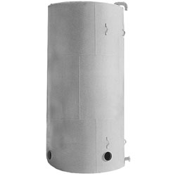
Stainless Steel
A stainless tank is hard to beat for liquid fertilizer storage, compatibility, strength, and lifespan are really unmatched by other tanks, however, this comes at a cost. Here are the pros and cons of stainless steel tanks for fertilizer storage:
Advantages of Stainless Steel Tanks for Fertilizer Storage
- Durability: Highly durable and resistant to corrosion, ideal for long-term storage.
- Strength: Can withstand high pressures and extreme temperatures.
- Hygiene: Easy to clean and does not support bacterial growth.
Disadvantages of Stainless Steel Tanks for Fertilizer Storage
- Cost: Significantly more expensive than other materials.
- Weight: Heavier, which can increase transportation and installation costs.
We supply stainless steel tanks manufactured by Precision Tank and Meridian Mfg. Whether you need a nurse tank, weight tank, or cone bottom storage tank, we can provide you a quote with the appropriate accessories to fit your truck, trailer, or building site.
Tank Size
Liquid fertilizer storage tanks are available in a range of sizes, typically from 1,000 to 30,000 gallons and beyond. The appropriate size depends on your storage requirements and application.
| Tank Material | Common Sizes (Gallons) |
| Poly | Up to 15,000 |
| Fiberglass | 8400 - 30,000 |
| Steel | 10,000-30,000 |
| Stainless Steel | 1700-6100 |
Tank Shape
Flat Bottom Tanks
Advantages
- Cost-Effective: Generally less expensive due to simpler design.
- Ease of Installation: Can be placed on various surfaces like concrete or gravel.
Disadvantages
- Incomplete Drainage: May retain some liquid at the bottom, which can be problematic for certain applications.
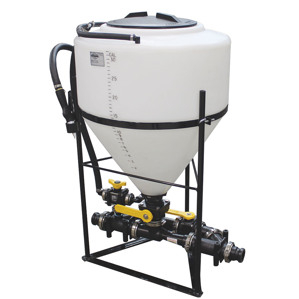
Cone Bottom Tanks
Advantages:
- Complete Drainage: Allows for total evacuation of contents, reducing residue.
- Ideal for Mixing: Beneficial when the complete drainage of mixed solutions is necessary.
Disadvantages:
- Additional Equipment: Requires a stand and possibly more complex installation.
- Higher Cost: Generally more expensive due to design and additional components.
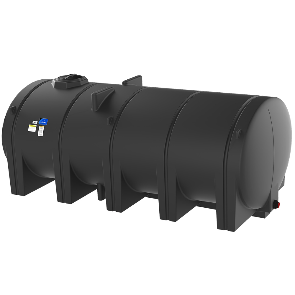
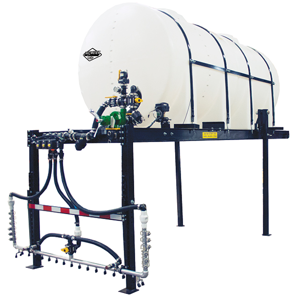
Horizontal Tanks
Advantages:
- Stability: Lower center of gravity provides stability during transport.
- Space Efficiency: Can be mounted on trailers or trucks for mobility.
Disadvantages:
- Limited Capacity: Typically smaller in size compared to vertical tanks.
Best Fertilizer Tanks for Various Applications
Fertilizer Dealer/Terminal Storage:
- Recommended Materials: Stainless steel or fiberglass for durability and corrosion resistance.
- Tank Shapes: Flat bottom tanks for large-volume storage; cone bottom tanks if complete drainage is necessary.
- Sizes: Larger tanks, ranging from 10,000 to 30,000 gallons
Bulk Storage on Farms:
- Recommended Materials: Polyethylene for cost-effectiveness and versatility; fiberglass for enhanced durability.
- Tank Shapes: Flat bottom tanks for stationary storage; Cone bottom tanks for mixing and complete cleanout.
- Sizes: Typically between 1,000 to 5,000 gallons, based on farm size and usage. Larger sizes available.
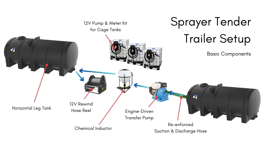
Nurse Trailers:
- Recommended Materials: Polyethylene due to its lightweight nature. Stainless for easy clean out and durability
- Tank Shapes: Horizontal tanks and elliptical leg tanks
Sizes: Generally 1,000 to 4250 gallons
Making the Right Choice
Dultmeier Sales can help you to find the best tank for your operation. Simply provide the necessary details about the liquid you want to store and we can help you through the process. Call us today for more information!


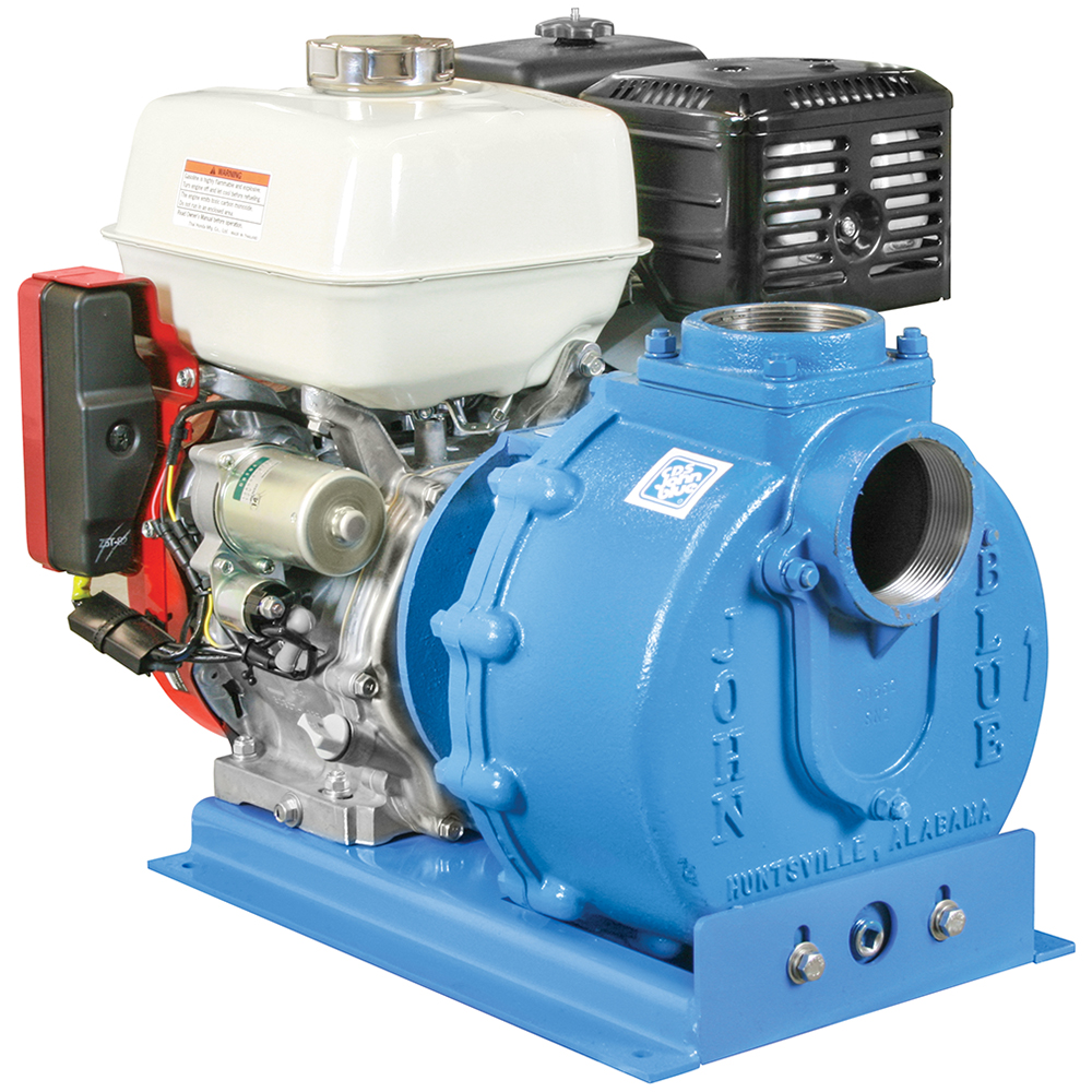


 Pump Selection Guide")