

Flow meters are some of the most versatile and integral components in any fluid handling system. From agriculture chemical production to water treatment facilities, meters offer a reliable means to monitor how efficient your operation is and provide a tangible reading to identify potential issues within the plumbing system. This makes choosing the right flow meter for your application even more important. Selecting the wrong meter causes inaccuracies within your flow monitoring processes and creates inefficiencies throughout the rest of the system, not to mention significant unintended costs.
Dultmeier Sales is here to ensure that doesn't happen.
In this guide to flow meter selection, we'll take a look at several common meter types and the various applications in which they are used. We will also highlight some key considerations to keep in mind so that you always choose the best flow meter for your application needs. So, without further ado, let's get started.
Understanding What a Flow Meter Does
Simply put, a flow meter is a device that measures the flow of material-typically either liquids or gases-through a pipe. It determines how much material passes through the pipe (or hose) in a given period. It typically provides this measurement in units like gallons per minute (GPM), liters per second (L/s), or cubic feet per minute (CFM).
While this concept is straightforward, selecting the right flow meter for your specific task, however, can be more complicated.
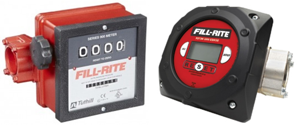
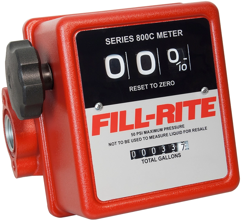
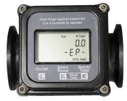
Fill-Rite mechanical flow meters & digital flow meters
How to Choose the Right Flow Meter
First off, It is important to note that no two meters are exactly alike. Depending on application and metering needs, you may have several meter options or a single very specific one from which to choose. Complicating things further are the many external considerations your meter must satisfy in order to accomplish its intended purpose. As they say, the "devil is in the details," and the same goes for choosing the best flow meter for your application.
Below are some key characteristics to keep in mind when selecting the proper flow meter:
- Accuracy & Repeatability
- Type of Fluid (liquid, gas, slurry, steam)
- Density
- Viscosity
- Conductivity
- Temperature
- Pressure
- Flammable/Oxidizer
- Corrosiveness/Toxicity
- Flow Range/Turndown
- Materials of Construction
- Environment/Location & System Configuration
- Hygiene Requirements (pharmaceutical, food processing, etc.)
- Costs
- Initial Investment
- Installation
- Long-term Maintenance
While the meter you ultimately select should ideally meet every factor above, ensuring it meets the most important ones for your operation will help guarantee you receive the best results. Let's dive into a few of the main ones on which you should focus.
Accuracy & Repeatability
Near the top of the list when evaluating flow meter specs is flow meter accuracy. Accuracy is how close a measurement is to the actual true value passing through a system. Expressed as a percentage (i.e. +/- 1%) accuracy represents how close the meter's output is to its calibrated parameters. Generally, the lower the percentage, the more accurate a meter is.
However, accuracy is not the only side of the coin. Repeatability, or the production of like outcomes under the same conditions, is perhaps even more important when evaluating which flow meter to choose. This is because accuracy is only reliable so far as its consistency. As you can see below, repeatability is possible without high accuracy, but high accuracy is not achievable without repeatability.

Flow meter accuracy & repeatability
If your flow readouts are unreliable-meaning you receive inconsistent results despite the same conditions-then you aren't gaining any value. Likewise, if your flow volume falls short of or exceeds your meter's rated flow range (also known as turndown), you won't receive accurate readings either.
Precision readings go hand in hand with any well-tuned operation. Choosing the best flow meter accuracy and repeatability percentages that meet your application requirements ensures your system maintains the precision readings you desire.
Liquid, Gas, or Semi-Liquid?
The type of fluid you work with is another big factor when choosing which flow meter best fits your application. Fluid type breaks into four categories: gas, liquid, slurry, and vapor-each with its own unique characteristics.
Properties such as fluid density, temperature, viscosity, and corrosiveness/acidity all must be determined before a final selection. This ensures you avoid choosing a flow meter incompatible with the fluid type you are attempting to measure. Electromagnetic flow meters, for example, won't work with non-conductive fluids like hydrocarbons. Likewise, few meter types are capable of measuring slurries because of their unique semi-liquid characteristics.
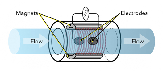
Illustration of how slurry particles behave between homogenous & heterogeneous mixtures
Here is a short list of flow meter types commonly used for the four fluid categories:
- Gas: Coriolis, Thermal Mass, Positive Displacement, Turbine, Variable Differential Pressure, Ultrasonic
- Liquid: Coriolis. Thermal Mass, Positive Displacement, Variable Flow, Paddlewheel, Turbine, Variable Differential Pressure, Ultrasonic, Electromagnetic
- Slurry: Coriolis, Electromagnetic, some subsets of Differential Pressure
- Vapor: Vortex, Ultrasonic, Floating Element
While not comprehensive, this list should offer a good starting point. That said, not every meter listed may work for your specific setup or needs. For instance, if your operation handles multiple fluids, you'll want to ensure that the meter you go with is compatible with all fluids-not just one. Otherwise, you likely spend valuable time calibrating your flow meter each time you handle a different product or troubleshooting why your inventories are off from your readouts.
Location & System Configuration
Meter location, as in real estate, is another major consideration. Will the flow meter be installed inside a controlled environment or outdoors in the elements? Is space a non-factor, or must size be considered? Certain flow meters even require stretches of straight pipe before and after the meter to generate accurate flow readings.
As a rule of thumb, pipe lengths of 10X (where X = pipe diameter) are needed before and after a meter for straight runs of pipe. So, if your plumbing's diameter is 2" you would need 20" or approximately 2 feet of pipe before and after the flow meter. This goes for just about any meter type, but it is always best to check the manufacturer's specs.
Also, keep in mind horizontal or vertical mounting. Some meters can be mounted in either orientation while others must be in one orientation or the other. Variable flow meters, for example, rely primarily on gravity in order to measure flow rate. Thus, they must be installed vertically to work. Determining how and where a meter will be installed while choosing a meter saves installation time and avoids costs related to unintended system reconfiguring.
Differentiating Between Volumetric vs. Mass Flow
Before we break down various flow meters, it is important to say a word on flow measurement. While there are many types of flow meters, most used today fall under two primary categories according to how they calculate flow: volumetric and mass.
As their name suggests, volumetric flow meters measure flow by calculating the volume of a fluid. Flow is often directed through an intrusion metering device such as a turbine or orifice plate, which then measures fluid velocity proportionally to the volume of matter passing by. Volumetric flowmeters make up the majority of meter types today and include turbine, magnetic, positive displacement, ultrasonic, and vortex meters to name a few.
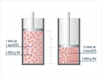
Volume flow vs. mass flow within a cylinder
Mass flow meters, meanwhile, calculate flow rate by measuring the mass of a fluid. Mass meters have become increasingly popular due to their precision performance and truer reading of product flow compared to older metering technologies. In the diagram above, for instance, the product volume significantly changes depending on the position of the piston-even as mass remains the same. Today, mass meters have more or less become synonymous with Coriolis mass meters, but other types do exist. We'll discuss how mass meters work later in the article.
Whether you choose volumetric meters and mass meters depends on your application and metering needs, as well as your operational preferences and cost differences. In the end, you can still calculate volume to mass or mass to volume so long as the fluid density, surrounding temperature effects, and other conversion factors are all understood.
Comparing Flow Meter Types
There is, unfortunately, no such thing as a universal flow meter. Each flow meter type has fluids and applications for which it is well suited, and similarly, ones for which they are not. The following is a breakdown of some of the most common types of flow meters and the pros and cons of using each one.
Positive Displacement Flow Meters
Pros
- Accurate across wide flow ranges
- *Can handle very viscous fluids
- Versatile applications-simple, reliable design
- Require no power supply
- Cost-effective
*Thicker viscosity fluids create larger pressure losses & reductions in flow rates
Cons
- Requires medium to high-flow applications
- Experience greater pressure drops
- Larger/heavier than other meters
- Not recommended for dirty fluids or gases
- Some subsets require constant lubrication
- Many moving components need regular maintenance and replacement
Positive displacement (PD) meters consist of chambers featuring mechanical components that rotate in relation to volume flow. As fluid passes through, the reciprocating components-generally a type of gear, vane, or diaphragm-divides the fluid into fixed, metered volumetric units. The number of units rotated through within a specified time frame directly correlates to flow rate. Subtypes include screw meters, rotary vane meters, diaphragm meters, reciprocating or oscillating piston meters, and helical or oval gear meters.
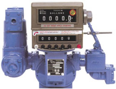
TCS 700 Series Rotary Fuel Meter with Register
Since PD meters only measure flow while fluid passes through, they're ideal for applications where metering is crucial to calculate fluid usage. The TCS 700 series rotary vane meters, for example, are widely used in oil and gas custody transfer industries, while diaphragm meters are commonly installed on residential or municipal water and gas lines. Their fluid-driven design additionally makes positive displacement flow meters one of the more cost-effective options since they require no outside power supply to operate. However, these meters are ill-suited for impure fluids such as wastewater or slurries, as the suspended soils can clog or slow the reciprocating elements and create inaccurate readings.
Electromagnetic Flow Meters
Pros
- Obstruction-less/No moving components
- Highly accurate-unaffected by density, viscosity, turbulence, or pipe configuration
- Can handle wide flow ranges & multiple fluid types
- Zero pressure drop
- Bi-directional
- Cost-effective
Cons
- Cannot measure gases, vapors, or non-conductive liquids
- Limited fluid temperature range
- Interference possible with certain suspended fluids
- Specialized subsets can be expensive

Electromagnetic flow meters, also known as magnetic flow meters or magmeters, are rather unique in the technology they use to measure flow. Magmeters feature two parts, a transmitter and an inline sensor, the latter of which features coils that generate a magnetic field. When a conductive fluid passes through the field, a voltage is produced proportional to flow. This flow principle is known as Faraday's Law.
Unlike other meters, magnetic flow meters can measure fluids regardless of fluid density, viscosity, or flow turbulence. This makes mag meters highly accurate and reliable across a wide range of solutions. Additionally, their design features no obstructions in the pipe, making these meters ideal for a wide spectrum of applications, from highly sanitary liquids to slurries and highly corrosive fluids. Electromagnetic meters can be found in industries such as pulp and paper, metals and mining, food and beverage, water and wastewater, chemical transfer, and many more.
Magnetic meters, however, only work with conductive fluids. This means hydrocarbons such as oils, gasoline, or deionized liquids are not recommended with mag meters. Suspended solids, such as those found in various ag chemicals and fertilizers, can also sometimes pose a problem. The suspended soils, which may not be conductive, can interrupt the magnetic field and throw off the reading's accuracy. Newer, specialized magmeters such as slurry magmeters are engineered to counteract this magnetic interference. However, these units generally feature heftier price tags compared to standard models.
Turbine Flow Meters
Pros
- Highly accurate
- Cost-effective
- Capable of measuring low flow rates
- Versatile applications-simple, reliable design
Cons
- Not recommended for dirty or suspended liquids
- Require straight pipe runs for best results
- Limited to certain pipe sizes
- High flow rates can cause damage or inaccuracies
- Moving components need regular maintenance and replacement
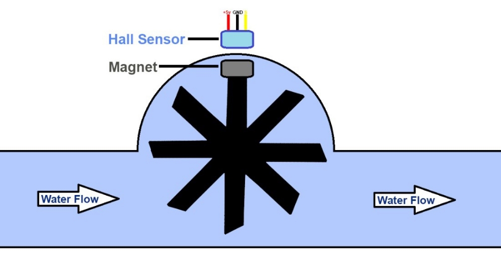
Like paddlewheel or propeller flow meters, turbine meters feature a multi-bladed rotor mounted inline to fluid flow. Sensors attached to one or more of the turbine blades transmit the number of revolutions the turbine makes. The speed at which these revolutions happen is proportional to volumetric flow rate. Similar to positive displacement meters, turbine and paddlewheel meters only measure flow when fluid mechanically acts upon their metering components.
Because turbine meters provide accurate readouts in relation to linear flow-even at low flow rates-they are widely used in the oil and natural gas, custody transfer, and petrochemical industries. In fact, turbine meters are often used to help verify the accuracy of other meter types.
Turbine meters aren't without their limitations, though. For starters, turbine meters are not well suited to handle dirty or highly viscous fluids, as the turbines can be easily fouled by the soils. These meters also require straight runs of pipe before and after the meter to stabilize flow for the most accurate results. Additionally, larger pipe diameters are incompatible from an engineering standpoint. This limits where and for what applications turbine meters can be installed. Finally, as with any technology with moving components, regular maintenance is necessary to keep these meters in peak-performing condition.
Coriolis Flow Meters
Pros
- Extremely accurate
- Low maintenance
- Can handle a wide spectrum of flow ranges
- Compatible with many dirty, corrosive & difficult to handle fluid types
- Versatile installation-no straight pipe runs required
- Serviceable without removing from the pipeline
- Easy in-field calibration
- Capable of measuring gases
Cons
- Expensive initial investment
- Not suited for low-pressure gases
- Limited to certain pipe sizes
Coriolis meters, more commonly known as mass meters, differ from other meter types in that they measure mass flow instead of volume flow. These meters also feature a unique means of calculating flow rate based upon the Coriolis Principle. Check out the video below for a quick look at Coriolis meter technology.
Advantages of Mass Meters
Mass meters generally hold an NTEP certification and are widely used in legal-for-trade (resale) applications. In the Dultmeier Sales world, this generally means fertilizers or chemicals with respect to the agricultural industry. Back in the 1990s, Dultmeier Sales partnered with Kahler Automation to offer some of the first automated solutions for fertilizer/chemical plant automation.
The mass meter was at the heart of the system because it was new technology that allowed end-users to sell using the real-time density of the product - a truer way to meter liquids. For example, water is known to be 8.34 lbs. per gallon at 70°F. However, as temperature drops, the weight of water increases. Thus, the solution of water becomes denser as the ambient temperature drops. This would mean static volumetric calculations would be off if one pumped 1000 gallons of water and converted to 834 lbs. (using 8.34lbs/gal as the constant conversion factor) if the water were only 50°F.
This same principle happens with fertilizer and chemicals - as they are generally water-based solutions. Volumetric meters of the time; however, were unable to account for this change in density in relation to volume flow. Take this scenario for example, which was quite common in the 1990s and early 2000s:
Let's say that it's 40° F. and we're loading a 10,000 gallon tender trailer, running 32% Nitrogen into the vessel. We're using a paddlewheel meter as our measuring device and pumping the product into the vessel. Once we reach our hit point of 10,000 gallons - the automated equipment shuts down and we send our trucker to the scale. The scale breaks in 20 lb. increments.
Our potential for error:
- Paddlewheel meter runs at approx. +/- 2% accuracy (mass meter is +/- .3% accuracy)
- Paddlewheel cannot determine density reading, so we have a static calibration factor that was calibrated at 70° F. (or another temperature) and we are using that static factor to now calibrate pounds to gallons at 40° F.
- Scale breaks in 20 lb. increments vs. mass meter measuring in increments of 1/10th of a pound
- Scale cannot account for "slosh" or movement of liquid as truck stops abruptly on the scale
Considering these many variables and the potential for error, it's no wonder why inventories could, and often would, be way off come year-end. We know that a solution's density changes constantly if in an ambient environment. For this reason alone, mass meter technology is the preferred method of measurement in many instances. By using a mass meter that can continually read this fluctuation in density on the fly, we offer our customers a better method to dispense and record inventory.
Today, Dultmeier works with Easy Automation Inc. to provide automated plant solutions using mass meters in addition to other state-of-the-art meters, controls, and equipment.
Flow Meter Price, Performance & Popularity
Unfortunately, there is no universal flow meter that works for every application. Depending on how diversified your operation is, that could mean multiple types of flow meters are needed. While it is fair to research the most popular meters for your industry, don't buy the first meter you think will work.
Price, quality, and other key factors do play a significant role in a flow meter's overall performance. Simply because everyone else uses a certain meter does not mean you should be. Low purchase cost, for instance, shouldn't be the deciding factor in choosing the best flow meter for your application. When choosing a flow meter, you have to consider not only the initial purchase price, but the overall lifetime costs and long-term returns on investment, too.

For instance, while a Coriolis meter boasts a hefty price tag at initial investment, it provides a great ROI because less maintenance and greater product savings are realized over the long run. Mass meters' exceptional accuracy, versatile flow ranges, and fluid compatibilities, minimal wearable parts, and the ability to recalibrate without removing the meter from the pipeline all translate to fewer dollars spent overall. When it comes to the bottom line, spending more money upfront can outweigh years of hemorrhaging dollars spent repairing or replacing inefficient meters.
That said, not every operation needs an expensive, high-end flow meter. It's a good idea to run a cost assessment evaluating application needs against initial investment costs and long-term cost savings. This way you have the best picture of whether a certain meter is practical or worth the price tag over the long haul. If you need help assessing meter options and determining what is best for your application(s), we are always just a phone call away at 1-888-677-5054.
Final Words
We hope this article has provided some insight into the world of flow meter solutions. Although we covered some of the most common types, these are by no means the only flow meters out there. Choosing the best type of flow meter for your application all starts with knowing what you need and researching your best options. Compare all associated costs-both short and long-term-and avoid making a decision based on price tags alone. Ultimately; however, the manner in which you choose to meter is entirely up to you.
If you have any questions regarding flowmeter selection, give us a call at 888-667-5054 or dultmeier.com. Dultmeier Sales carries a diverse inventory of chemical and water flow meters, flow meter repair parts, and flow meter accessories. No matter what meter your operation requires, our experience and technical expertise will help make sure you select the right one.