

Whether you're dealing with weeds, insects, or applying fertilizer, selecting the right sprayer nozzle plays a crucial role in the effectiveness of your results. Nozzles affect the rate, coverage, drift potential, and other performance characteristics of your spray applications. But how do you choose the perfect nozzle for your needs? The answer lies in understanding spray nozzle charts.
Spray charts provide you with all the details you need to make an informed decision. However, if you are not familiar with them, all the information these charts provide can be hard to sift through. If you want to learn how to use a nozzle chart, stick around because in this guide we will walk through all the information these tools provide and how you can become more confident in reading these charts accurately.
Understanding the Information Included in a Spray Nozzle Chart
A spray nozzle chart is a detailed table that provides comprehensive performance data for a specific sprayer nozzle series. It displays essential information about the nozzle's performance characteristics, such as flow rate, droplet size, and pressure ranges. Understanding how to read a nozzle chart, therefore, is crucial for selecting the appropriate spray nozzle for your specific needs.
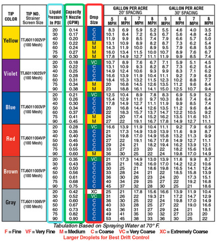
TeeJet Spray Nozzle Chart Example:
The primary purpose of spray nozzle charts is to guide applicators in making an informed decision when choosing a sprayer nozzle. To use the chart effectively, you must understand the information being presented.
So, let's look at the different pieces of data shown in nozzle charts.
Nozzle Capacity (GPM)
The most essential piece of information that a nozzle chart shows is the flow rate of a single nozzle in gallons per minute (GPM) at different pressures. It is important to note that regardless of which nozzle type you are looking at, the flow rate/capacity will be the same across all the different nozzle sizes.
This allows users to select the proper nozzle size according to their application parameters.For help sizing your nozzles, you can refer to our complete guide to properly sizing sprayer tips.
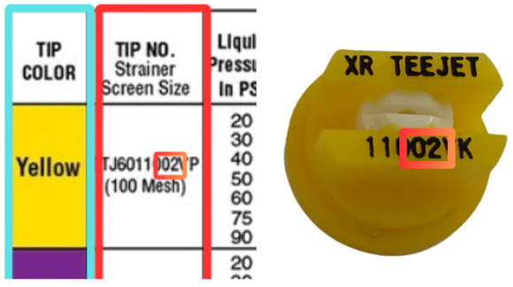
Spray Nozzle/Tip Numbers & Colors
Sprayer nozzles used for agricultural and turf spraying are color-coded and abide by an international standard. These standards set criteria so that nozzles across different brands and nozzle types/series can be compared equally.
In simple terms, a yellow-colored or "02" size nozzle in one series will have the same flow capacity as a yellow nozzle from another brand or spray nozzle series. You can find the different sizes/colors and their part numbers in the far-left column of a sprayer nozzle chart:
For additional details on how to understand spray nozzle sizing, refer to our guide to understanding sprayer nozzle numbers.
Operating Pressure
The operating pressure directly influences the flow rate of the nozzle, which is the amount of liquid that passes through the nozzle per unit of time, typically measured in gallons per minute (GPM). A range of operating pressures is displayed to show the capacity (flow rate) of each nozzle size at various PSI.
As pressure increases, the flow rate generally increases as well. A spray chart allows you to see how much liquid the nozzle will dispense at each specified pressure level. This is vital because two different nozzle sizes may deliver the overall GPM you need, but they will do so at different pressures. You must match the flow rate and operating pressure you prefer in order to maximize tip performance.
Droplets Size
Another significant factor influenced by operating pressure is droplet size. Just as flow rate changes with pressure so too can the droplet size also change. However, while the flow capacities remain the same across nozzle sizes, the droplet sizes produced by the different sizes at various pressures will vary between different types/families of sprayer nozzles.Spray nozzle charts provide the average droplet size a nozzle produces at different operating pressures.
Again, droplet size is one of the most vital aspects of a sprayer nozzle to get right because it impacts factors like spray coverage and drift which determine your application's effectiveness. For more details on how to understand this aspect of sprayer nozzles, be sure to read our full guide to spray nozzle droplet size.
Using a Spray Nozzle Chart to Identify the Right Nozzle
While understanding the information that is presented in a sprayer nozzle chart is vital, it is only half the equation. You also must understand how to use it to narrow in on the best nozzle for your needs. Here's a simple step-by-step guide to help you navigate the chart and select the perfect nozzle for your specific application.
Determine Your Application Requirements
The first step involves gathering the details of your application. Here is the information you need:
- Application Rate: How many gallons per acre (GPA) you need to apply.
- Ground Speed: The speed at which you'll be operating the sprayer (MPH).
- Spray Pattern Spacing: The spacing between your nozzles on the boom (most commonly 20" or 30").
- Desired Droplet Size: Based on the type of chemical and drift potential as recommended by your chemical labels.
With this info, you can calculate the gallon per minute (GPM) flow rate you need out of a nozzle to achieve your desired application rate (GPA). Here is the formula to determine this:
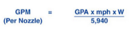
You can see a full walkthrough of how to use this formula as well as a calculator that will do the work for you in our guide to calculating nozzle/orifice size.
Find Your GPM In the Chart
Once you have determined the flow rate you need out of each nozzle, you can search for that flow rate in the capacity column. The nozzles are listed from smallest to largest capacity, starting at the top. You'll simply follow the column down until you arrive at your flow rate.
Note, you may discover several different sizes of spray tip will work for your desired flow rate, but that doesn't necessarily mean each nozzle is equally right for your application. There are other factors to consider as discussed above that you'll want to check, too.
Identify the Corresponding Nozzle
Next, follow the row horizontally to the left to find out the PSI that will produce your flow rate with that nozzle. If that PSI is too low or high for your application, then look at the next nozzle size and find out what operating pressure will produce the GPM you need. Continue this step until you find a nozzle that matches both your desired flow rate and operating pressure.
Verify Droplet Size
Confirm the droplet size classification meets your requirements (e.g., Medium, Coarse) as recommended by the product label. Droplet size typically decreases as pressure increases, so this means that two different sized nozzles can potentially produce the same flow rate but create different droplet sizes.
Droplet size is a complex topic that can have a significant impact on the effectiveness of your pesticide/herbicide application. If you would like a full breakdown, please read our guide on
Example
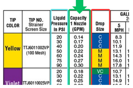
Let's suppose you need to apply 15 GPA at a ground speed of 6 MPH with nozzles spaced 20 inches apart. If we enter these numbers into the GPM formula we get 0.30 GPM. This is the number we need to find in the nozzle chart.
In our example, we are using the chart for TeeJet Turbo TwinJet (TTJ60) nozzles, but this process is the same for most flat fan sprayer nozzles regardless of the brand:
You can see that our flow rate (0.30 GPM) can be produced by four different nozzle sizes albeit at different pressures. This is common. What you want to do is look at the pressure column just to the left to see what operating pressure would produce this flow rate. Typically, you would want to choose the nozzle that will deliver 0.30 GPM near the middle of the pressure range.
Choosing a nozzle size that delivers your flow rate in the center of the pressure range provides you room to speed up or slow down as you spray. You would just need to increase or decrease your pressure accordingly.In this example, you would likely settle on the 025 size (violet) or 03 size (blue) nozzle.
Depending on your application, you may opt for a nozzle size that can deliver 0.30 GPM while maintaining a certain droplet size. The blue nozzle will result in a spray pattern that will have most of the droplets fall into the Coarse size range. The violet-size nozzle also produces a coarse droplet, however, if you were to speed up and increase your pressure it is possible that most droplets would fall into the Fine category.Depending on the chemicals that you are spraying, this change in droplet size may not fall within the recommended and approved droplet range, increasing drift potential ineffectiveness or risk for your spray area (and those areas around it).
The various families/types of nozzles will produce a range of different droplet sizes. This specific type of nozzle produces a relatively small droplet across the different sizes compared to other nozzle types, such as air induction nozzles. It is important to consider your application and consult the label of any product you are using to find help deciding the appropriate droplet size.
Specific Scenarios
Many nozzle charts, such as the one referenced earlier, will display the specific flow rate of a spray nozzle across a range of speeds when used at certain spray nozzle widths. In the chart above, you can see the flow rates for each nozzle size when spaced at both 20 and 30 inches apart on a sprayer boom.
This can help you identify the nozzle sizes that will work for your application rate without having to calculate your GPM. Of course, this is only applicable if your nozzles are at that specific spacing and you travel within the provided speed range.
Conclusion
Understanding spray nozzle charts is key to making informed decisions and optimizing your spraying operations. By following the steps described today, you can use spray charts to identify the most suitable nozzle for your specific application requirements.
You can find charts for specific spray nozzles on our product pages for each nozzle type:
If you're still uncertain about which nozzle is right for your needs or want to explore more about spray nozzles, contact our agriculture sales team for assistance.