Search
Call for Live Order Assistance & Technical Support (7:30am-5pm CST)
All Categories
    Menu Close
    RSS

    Blog posts of '2024' 'November'

    Air-Operated Double Diaphragm (AODD) Pump Selection Guide
    Air-Operated Double Diaphragm (AODD) Pump Selection Guide

    Air-operated double diaphragm (AODD) pumps are highly versatile, reliable devices widely used across various industries for handling viscous, abrasive, and shear-sensitive fluids. Powered by compressed air, these pumps use two diaphragms in a reciprocating motion to transfer liquid. With no need for electricity, these pumps offer a versatile option for hazardous and demanding environments.

    AODDs: Basic Parts and Operation

    1. Diaphragms: Located on either side of the pump, the diaphragms are flexible membranes typically made of materials like PTFE or rubber. 
    2. Air Chamber: The air chamber (also known as the air valve chamber) is where compressed air is introduced to alternate between the two diaphragms. 
    3. Inlet and Outlet Manifolds: The inlet manifold allows the fluid to enter the pump chamber, while the outlet manifold directs the fluid out of the pump after it has been moved by the diaphragms. 
    4. Check Valves: Each diaphragm chamber has two check valves, one at the inlet and one at the outlet. These valves are responsible for directing fluid flow in a single direction. Typically a ball and seat style check valve.  
    5. Valve Assembly (Air Valve): The air valve assembly, typically located in the center section of the pump, controls the distribution of compressed air to the diaphragms. 
    6. Fluid Chambers: Fluid chambers are located on either side of the diaphragms. 
    7. Exhaust Port: As compressed air pushes one diaphragm, the air on the opposite side is expelled through the exhaust port. This port vents the air used to move the diaphragms, and in some applications, exhaust air is collected or muffled to reduce noise.
    8. Center Section: This is the core of the pump, housing the air valve and the air distribution system. 
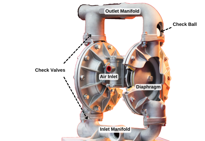
     

    AODD Pump Parts Explained


    How These Parts Work Together

    When the pump starts, compressed air is directed into the air chamber behind one of the diaphragms, causing it to push outward and transfer fluid out through the outlet manifold. Simultaneously, the opposite diaphragm is pulled inward, creating suction in its fluid chamber, drawing in new fluid through the inlet manifold. The air valve then alternates the air supply to the other diaphragm, repeating the process. This alternating motion allows AODD pumps to handle viscous, abrasive, and shear-sensitive materials efficiently and reliably.


    This design makes AODD pumps ideal for industries where the safe handling of various fluid types—especially in explosive or corrosive environments—is essential. 


    Advantages of an AODD Pump

    1. Corrosion Resistance

    Advantage: Built with materials like PTFE, Viton, and Santoprene, AODD pumps can handle a wide variety of fluids, including those that are abrasive, viscous, corrosive, or contain solids.

    Benefit: This versatility allows them to be used in many different industries and applications, from chemical processing to food and beverage production.

    2. Self-Priming Capability

    Advantage: AODD pumps are self-priming, meaning they can start pumping without needing to be filled with fluid first.

    Benefit: This makes them ideal for applications where the fluid source is below the pump or where frequent starts and stops are required.

    3. Ability to Run Dry

    Advantage: AODD pumps can run dry without damage, unlike many other pump types. This means operating the pump without fluid moving through it.

    Benefit: This is valuable in situations where the fluid supply may be inconsistent or may be interrupted. For example, you could use an AODD to pump out the contents of a barrel without needing to monitor the liquid level and shut off the pump immediately when the barrel is emptied to avoid damage to the pump. 

    It should be noted that although an AODD pump can run dry, prolonged operation with no fluid can be hard on the diaphragms and other components. 

    4. Safety 

    Advantage: While not all AODD pumps are inherently explosion-proof, they are powered by compressed air and don’t require electricity, eliminating the risk of sparks.

    Benefit: This generally makes them safe for use in hazardous environments where flammable or explosive materials are present, such as in the oil and gas industry. Always be sure to check that your pump and pump materials are compatible and designed for your application and environment.

    5. Gentle Pumping Action

    Advantage: The reciprocating diaphragm movement in AODD pumps produces a gentle, low-shear pumping action compared to other pump types. 

    Benefit: This makes AODD pumps preferable for handling shear-sensitive fluids, such as emulsions, suspensions, and biological materials, without damaging them.

    6. Easy Maintenance

    Advantage: AODD pumps have relatively simple designs with few moving parts, making them easy to maintain and repair.

    Benefit: Maintenance can typically be performed on-site without the need for specialized tools, reducing downtime.

    7. Pumping of Solids and Slurries

    Advantage: AODD pumps can easily handle fluids containing solids or slurries without clogging.

    Benefit: This capability is crucial in industries like wastewater treatment, mining, and construction, where the fluid being pumped often contains particles or debris.

    8. Simple Control

    Advantage: The flow rate of AODD pumps can be easily adjusted by regulating the inlet air pressure without the need for complex controls.

    Benefit: Common air regulators are all that is required to adjust the pump. A simple ball valve can be used to turn the pump on and off.

    9. Suction Lift Capability

    Advantage: AODD pumps can achieve significant suction lift (30 feet or more!), making them capable of drawing fluid from deep or difficult-to-access locations.

    Benefit: This makes them useful in situations where the fluid source is located below the pump, such as in sump pits or underground storage tanks.


    Specific AODD Pump Applications Across Industries

    The unique design of AODD pumps allows them to fit into several different applications. Let’s examine some specific scenarios where an AODD pump can excel while other transfer pumps fall short.

    Safe Transfer of Corrosive and Hazardous Fluids

    In the chemical industry, AODD pumps are essential for safely transferring corrosive and hazardous substances. Their seal-less design significantly reduces the risk of leaks, enabling secure handling of acids, solvents, and aggressive chemicals.

    Specific applications: AODD pumps with poly body and Teflon diaphragms can be used to pump high concentrations of phosphoric acid and Kynar body pumps with Teflon diaphragms can handle sulfuric acid. 

    AODD Pumps in Food and Beverage Production

    AODD pumps are widely utilized in the food and beverage sector to handle products like sauces, syrups, and beverages. Their mild pumping action preserves the quality and consistency of materials that can change in viscosity when agitated or stirred (creams, sauces, condiments, etc.).

    Specific applications: There are also AODD pumps designed for handling large solids and slurries associated with the meat and poultry processing industries. These pumps are sanitary pumps designed for quick and easy cleaning. Typically featuring high-grade stainless-steel bodies.

    Mining and Construction: Heavy-Duty AODD Pumps for Slurry and Dewatering

    Mining and construction industries present unique and rugged applications. The need for dewatering dirty water and sludge where the contents and solids sizes are often varied and unpredictable. The right AODD pump can withstand tough environments. They are also portable and can run dry without damage, making them a reliable choice in these demanding fields.

    Specific Application: Warren Rupp offers durable pumps with metal bodies (aluminum, cast iron, stainless). The Sandpiper Beast is a tough, clog-resistant pump designed to move fluids with debris up to 2 inches in diameter.

    Petroleum Industry

    In the oil and gas industry, AODD pumps move crude oil, gasoline, diesel, and other petroleum fluids. The pumps’ lack of electrical components provides explosion-proof safety, making them ideal for hazardous environments. 

    AODDs are ideal for handling oils and hydraulic fluids of various weights making them a versatile option for fleet maintenance. 

    Specific Applications: The Zeeline NS1040UL is a UL-rated AODD that will safely pump gasoline and diesel fuels up to 37 gallons per minute. 

    AODD pumps also work excellent for handling waste oil

    Car and Fleet Wash

    Transferring different soaps, detergents, wax, and sealers requires a pump that can move the fluid without resulting in foaming. It also must handle a wide range of different chemical combinations and viscosities.  

    Specific applications: This Yamada poly pump is versatile and has wide chemical compatibility for soaps, detergents, and other cleaning products. 
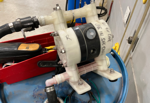
     

    AODD pump for soap


    What Materials are AODD Pumps Made From?

    AODD pumps are constructed from a variety of different materials. Different materials are used for the main components: the housing, check valve balls, seats, and diaphragms. 

    The housing (or body) of an AODD pump consists of the fluid chambers and inlet/outlet manifolds. Common materials include:

    • Aluminum: Lightweight and suitable for oils, coolants, and certain solvents but may corrode with acidic or abrasive fluids.
    • Stainless Steel: Durable and resistant to corrosion, making it ideal for food, beverage, pharmaceutical, and certain chemical applications.
    • Polypropylene: A cost-effective, lightweight plastic that resists a wide range of chemicals. 
    • Kynar (PVDF): A chemically resistant plastic with excellent durability, often chosen for aggressive chemicals like acids and solvents.
    • Cast Iron: Highly durable but susceptible to corrosion with certain chemicals. They are commonly used for demanding applications in construction and mining. 

    The check valve balls are in direct contact with the fluid and must be resistant to the medium you are pumping. Common materials include:

    • Santoprene: A thermoplastic elastomer with good chemical resistance, typically used for water-based fluids and certain chemicals.
    • PTFE (Teflon): Highly resistant to chemicals, suitable for aggressive solvents, acids, and high-temperature applications.
    • Nitrile (Buna-N): Good for petroleum and certain chemicals but less resistant to extreme temperatures.
    • Viton: Excellent for high-temperature and a variety of chemical applications.

    Seats create the sealing surface for the balls, and their material affects the pump’s fluid compatibility. Common seat materials:

    • Polypropylene
    • Stainless Steel
    • Santoprene and Buna-N

    Diaphragms are crucial in AODD pumps, as they directly handle fluid and pressure. The choice of diaphragm material influences chemical resistance, flexibility, and temperature tolerance.

    • Santoprene: A flexible, durable option for a range of chemicals, commonly used in general applications.
    • PTFE (Teflon): Excellent chemical resistance, suitable for aggressive fluids, and has a longer lifespan in abrasive applications. 
    • Buna-N (Nitrile): Good for petroleum-based fluids and general applications but limited by lower chemical and temperature resistance.
    • Hytrel: A thermoplastic polyester with good chemical resistance, flexibility, and durability for various industrial fluids.


    AODD Pump Limitations

    The AODD family is very versatile and offers unique benefits but there are some limitations:

    Requires Continuous Air Supply

    AODD pumps need a reliable, continuous supply of compressed air to function. In remote locations or applications where compressed air is not readily available, additional equipment (like air compressors) may be needed, adding to setup costs.

    Efficiency and Air Consumption

    AODD pumps rely on compressed air to operate, which can lead to high air consumption, especially when running at high flow rates or under heavy loads. This can increase operating costs.

    Compared to other types of pumps (like centrifugal pumps), AODD pumps typically have lower energy efficiency. This can be a drawback in applications where energy efficiency is a primary concern.

    If energy efficiency is a priority, Graco offers electric motor-driven double diaphragm pumps. This provides you with the benefits of an AODD with significantly lower (up to 80%) operating costs. 

    Pulsing

    The “back and forth” nature of the pumping operation can result in a pulsating flow. This can be mitigated with pulsation dampeners, but it may still not be ideal for applications requiring a steady, continuous flow.

    Pressure

    An Air-Operated Double Diaphragm (AODD) pump typically operates at a maximum pressure of around 100 psi, although certain specialty models can handle higher pressures. These pumps are generally not suitable for high-pressure applications that exceed their design limits. Most AODD pumps have a 1:1 pressure ratio, meaning the liquid discharge pressure matches the air inlet pressure. For example, if the air supply is set to 50 psi, the pump will produce a liquid discharge pressure of approximately 50 psi.


    Ready to Choose the Right AODD Pump?

    Explore our selection of Air-Operated Double Diaphragm (AODD) Pumps, tailored for a wide range of applications. Our team is ready to assist you in finding the perfect pump for your industry’s needs.

     

    Shane Blomendahl, Author

    Tech Ag & Industrial Sales

    Shane Blomendahl is a tech sales veteran at Dultmeier Sales with over 10+ years of experience in liquid handling products covering several industries and applications.

    Learn More About Author

    Complete Guide to Planter Fertilizer Systems
    (0) Complete Guide to Planter Fertilizer Systems

    Corn, or any crop for that matter, requires nutrients to grow. In the pursuit of better yields the need for precise and timely application of these nutrients is almost as crucial as the type of nutrient itself. Accomplishing this often means applying liquid fertilizer even at the planting stage. 

    Accomplishing this requires a liquid delivery system on your planter. Today we are going to look at a variety of system options, explain their pros and cons, and determine what systems are best for a variety of scenarios.  

    Article Table of Contents - Click to Jump to a Section:


    Basic Planter Fertilizer System Overview

    For the purposes of this article, when we refer to different types of fertilizer systems, we are talking about the complete collection of equipment and devices used to deliver the liquid fertilizer. Including the pump, controls, hoses, valves, flow meters, etc. These systems vary widely in their complexity from the simpler systems with 12-volt pumps, to the more elaborate automatic systems with electronic flow monitors for each row. 

    Many Options to Choose From

    There are numerous options for each component of a planter fertilizer system because every operation has unique needs based on factors like fertilizer type, equipment, and budget.

    Putting a system together requires consideration of these factors and ultimately selecting the components that provide the features you want while remaining easy enough to install and operate. 


    Fertilizer System Overview

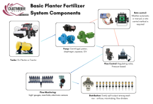
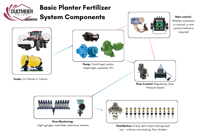
    We will get into more details about different types of systems in a moment, but first, let’s look at the basic layout of a fertilizer system. While different fertilizer methods (2X2, in-furrow, etc.) will require some slight variations, these basic components are going to be required in some form.


    Fertilizer System Diagram

    Fig. 1 Fertilizer System Diagram

    Fertilizer Tanks

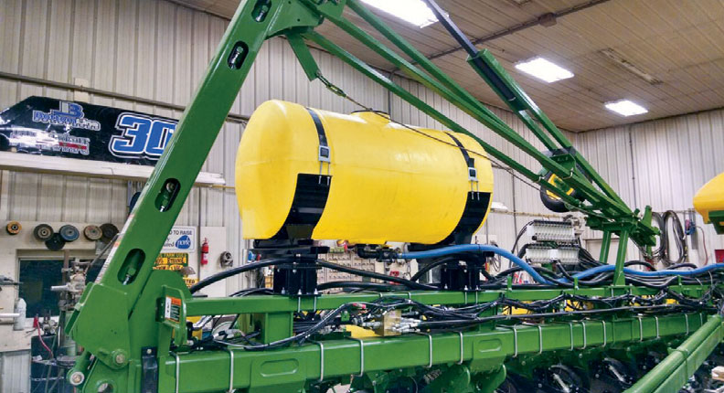
    Poly tanks are the go-to option for a wide range of fertilizers, agrochemicals, and soil biologics. Most tanks used in fertilizer delivery systems are either mounted on the planter or the tractor. No matter which setup you prefer, there are kits to accommodate several different planter makes/models as well as saddle tanks and helicopter tanks for tractors. 

    You can browse the various tank options here:

    Planter Fertilizer Tanks

    Planter Fertilizer Tanks

    Tractor with front and side tanks mounted

    Tractor Tanks


    These kits make it pretty easy to identify a tank or set of tanks that will fit your equipment, but there are dozens of other tank sizes and shapes available if you are looking for something to fit a unique scenario. 


    Rate Control

    When it comes to controlling the system, there are two primary categories: automatic and manual control. Rate control refers to the mechanism used to change the volume of liquid applied. Simply put, you can opt for a system that automatically adjusts the flow as you speed up or slow down or one that requires you to manually make the adjustment. 

    Manual rate control systems are generally going to be simpler to use and less expensive. This also means, however, that they lack the convenience of automatic rate control systems. Typically, they do not accommodate prescription applications or data collection as an automatic system might. If you want more information, look at this comparison between auto and manual rate control


    Pump Type

    Pump type is another vital aspect to consider, and the main types used for fertilizer application are centrifugal, diaphragm, piston, and squeeze pumps. Here are the pros and cons of using each type:

    Pump Type

    Pros

    Cons

    Centrifugal High volume, easy maintenance, long service life (especially stainless steel), good for prescriptions Requires hydraulic outlets, cannot run dry (unless wet seal), more expensive, not self-priming
    Diaphragm Handles viscous products, self-priming, can run dry, higher-pressure capability, flexible installation Lower flow compared to centrifugal pumps, requires a pressure relief valve, and routine maintenance needed
    Piston Extremely accurate, durable construction, can prime from longer distances, ground drive models maintain application rate with speed changes Lower flow rate, not ideal for abrasive products, potential for pulsating flow from piston stroke
    Squeeze Simple setup, maintains rate with speed changes, stops when the planter stops, minimal additional components needed Less versatile, limited pump sizes and row configurations available
    12V Diaphragm Low cost, compact, easy to install, simple to operate, adjustable output with rheostat control Limited flow rate (3-6 GPM), not suitable for large planters, can overheat with continuous use or rapid stopping and starting


    For more details on each pump type, be sure to read our article about choosing the best fertilizer pump for your planter.


    Blockage Monitoring 

    Monitoring fertilizer applications is essential for efficient application. Accurate flow monitors help to prevent overuse that can harm plants and waste money. Monitoring systems detect clogs early, preventing missed application areas.  

    Just like with pumps and controls, there are blockage monitoring systems ranging from simple to more complex electronic meters.

    “Redball”/”VisaGage” Sight Gauges

    The most basic monitoring option is the liquid flow sight gauges also known as “Redball” monitors or “VisaGage” monitors. Several different companies make a version of these tools, but they all function the same.

    They consist of a series of clear vertical tubes, each corresponding to a specific row. As liquid flows through the system, colored indicator balls rise in the tubes, showing the flow rate for each row in real-time. If one ball is significantly lower or higher, it signals a potential issue that the operator can address.

    Flow monitors like Redball and VisaGage use color-coded balls with specific weights to indicate flow rate ranges. Lighter balls, suitable for low flow rates, require less pressure to lift, while heavier balls are designed for higher flow rates and pressures. Intermediate-weight balls cover medium ranges. The color coding allows operators to quickly and visually confirm the flow rate, simplifying monitoring and eliminating the need for manual measurements.

    Every brand offers their version of visual spray monitor variations to work with different pump types and system setups. There are manifold versions and squeeze pump versions, with threaded or push-to-connect ports. You can check out the various options available here:


    Electronic Flow Sensors

    In some instances, it can be hard to see the balls in the visual monitors due to the dark color of fertilizer or biological product. Unlike traditional visual flow columns, electronic flow monitor systems provide an audible alarm when a row is potentially blocked, ensuring operators can address problems quickly. Several electronic flow monitor systems exist that allow you to monitor all the rows on a console in the cab of the tractor:

    CDS-John Blue Liquid Blockage Monitors (LMBS)

    John Blue offers blockage monitor sensors that can be added to their visual monitors. These sensors have magnets that sense the ball inside the flow monitor columns, and when a ball drops below the desired range the system gives you a visual and audible indication on a display in the cab. 

     John Blue offers both a wired version with a simple display panel and a wireless version that can be paired with an iPad. The wireless iPad version provides a visual indication of the ball levels in each monitor while the simpler wired version only provides an indication if there is a block.

    Wilger Electronic Flowmeter (EFM)

    The Wilger EFM is an electronic flowmeter which installs in the liquid line of each row. The EFM uses a paddle wheel to measure the flow rate and sends a wireless signal to a tablet in the cab. Both color-coded visual indicators and audible alarms can be set to user preference for near-instantaneous monitoring of each row. The Wilger EFM system can monitor up to 196 separate rows, up to 10 sections, and can be easily retrofitted to your existing visual spray monitors. 

    Layout Diagram of 24 Row Crop Spray System

    Check out the Wilger EFM system here


    Distribution

    While major components like the tanks and pump may be the costliest items, your distribution system should not be overlooked. If you do not have the proper method to evenly divide the fertilizer over each row, your ROI will greatly decrease. 

    Flow dividers, orifices discs, and microtubing are all viable options, but how do you decide which one to use?  Well, the type of pump you use will ultimately determine which route you take. Let’s look at the primary methods of flow distribution and when to use them.  


    Orifices Discs

    Orifices are small stainless discs that control the flow rate by restricting the flow of liquid. Orifice discs are a simple and cost-effective distribution method which are typically used in 12V or centrifugal pump systems. They can be used as the nozzle or outlet and “dribble” fertilizer on the ground or installed inline ahead of a fertilizer rebounder or stainless tube.

    Orifices can also be installed on the top of the visual flow monitors (Redball). The benefit of this is less components down near the row unit that can get plugged up or potentially damaged. 


    Orifice Disc with Gasket and Nozzle Body

    *Stainless orifice disc and 18999EPR gasket installed in check valve nozzle bodies and cap.


    Microtubing

    One drawback of using orifice discs is that they are prone to plugging, especially when using products that have suspended solids in them.  , on the other hand, provides the same metering ability as an orifice with a larger fluid path, and this larger fluid path reduces the risk of blockages happening.

    Different size diameters of tubing correlate to different flow rates (GPM).  The tubing acts like an orifice, restricting the flow to deliver certain flow rates at various pressures. The difference is that the inside diameter of the tubing does not need to be as small as an orifice that provides the same relative flow rates because the friction loss of the fluid is extrapolated out over the entire length of tubing. In short, the fluid passes through a wider opening and has less risk of plugging while still delivering the same flow rates. 

    Microtubing is a great option with soil biologicals and really viscous fertilizers. You can check out the different Identifying the proper size requires doing some math, you can reach out to us for help. 


    Flow Dividers

    A flow divider is a device that splits the liquid that enters it evenly across each outlet. It is not simply a manifold; it is specially designed for even distribution. There is no need for orifices or additional metering as there would be with a basic manifold.  

    Flow dividers are used with ground-drive piston pumps. The total rate you want to apply per acre is set on the pump. Whatever the incoming flow rate from the pump, the divider splits it up accurately.

    Explore John Blue Flow Dividers


    Fertilizer Placement

    Getting the fertilizer delivered to the desired target is vital. In many cases, the fertilizer is simply dribbled on the ground but there are specific tools for in-furrow/pop-up and 2x2 applications. Totally Tubular stainless steel placement tubes are precision-engineered for several planter models and will allow you to apply fertilizer efficiently.


    Planter Fertilizer Setup Examples

    12-Volt Pump Fertilizer Systems

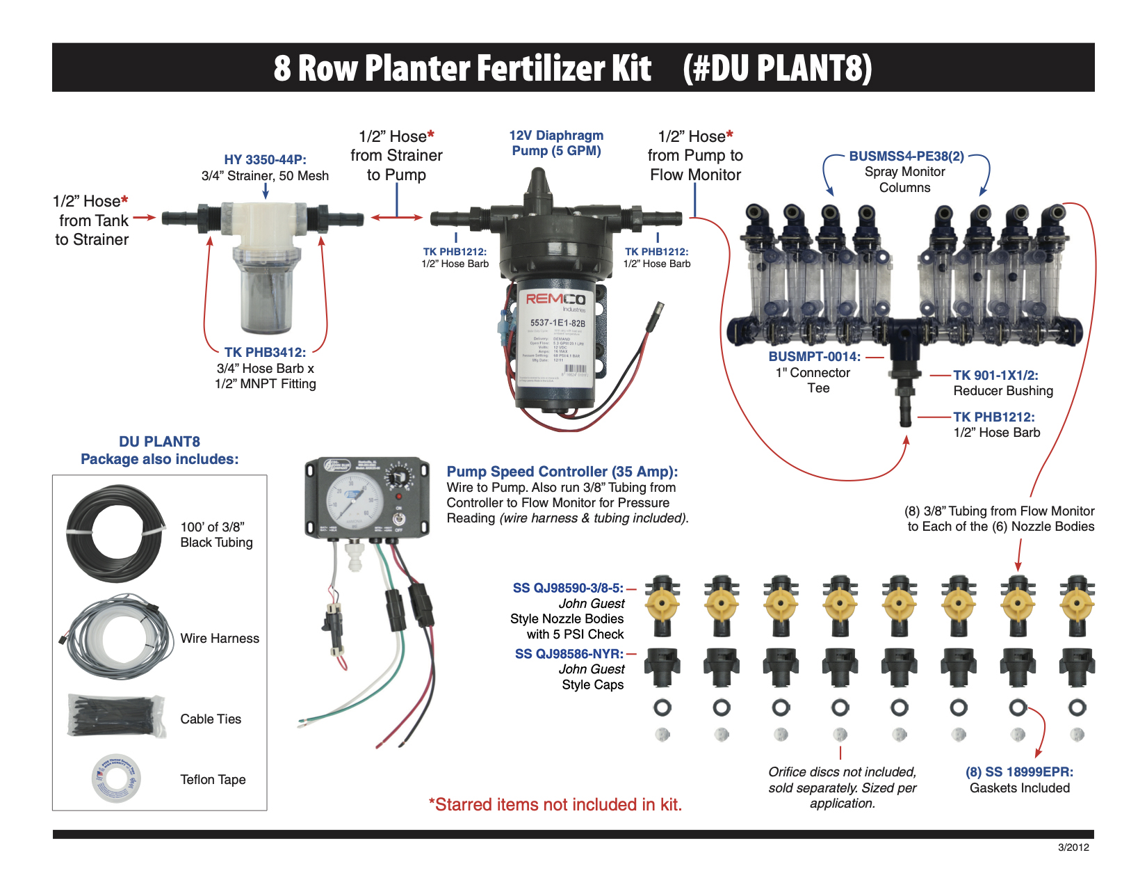
    Building your planter fertilizer system around a 12V pump is a low-cost, simple option. The basic setup would include the pump, pump speed controller, flow gauges, check valves, and orifice discs. In addition to these pieces, you will also need hose, fittings, zip ties, etc. 

    Here is what this complete setup looks like: 

    Example of 8 Row Planter Fertilizer Kit

    Dultmeier offers pre-boxed kits that contain components for 6-, 8-, 12-, and 16-row planters. These kits can also be customized for drills or planters with any number of rows or dual product placement needs. You can also easily upgrade from the basic sight gauge monitors to electronic flow monitors if desired.  You can see all the options


    12-Volt Fertilizer Pump System Pros 

    • Low cost
    • Simple to setup
    • Simple to troubleshoot

    12-Volt Fertilizer Pump System Cons

    • 12V pumps not a long-term option as the motors and internals tend to wear out sooner compared to other pump types.
    • Rapid pump cycling can lead to overheating
    • Limited to about 5 gallons per minute flow rates


    A 12-volt pump system will typically be adequate for 5-10 gallons per acre on 12-row planters traveling up to about 5 mph. You can use this GPM calculator to help determine the flow rate you will need from your pump. If you need to apply a rate above 10 GPA or have a planter larger than 12 rows, a centrifugal pump may be the right choice for you. 

    You can replace the 12-volt pump in the above kit with a hydraulic-driven centrifugal pump and use all the same components except the speed controller. Instead of the speed controller, you will need a rate control console and regulating valve or a rate control console and pump equipped with a PWM motor. 


    Ground Drive Fertilizer Systems

    Another simple planter fertilizer option is to utilize a ground drive pump. It offers automatic rate adjustment because the pump is driven by a planter shaft or ground drive assembly, the speed of the pump changes in direct relation to the speed of the planter. This is accomplished without the need for a rate controller or other electronics. 

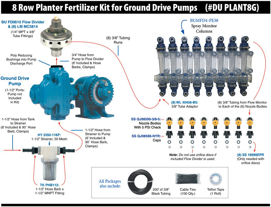
    In addition to the pump, the other key components are the flow divider and the spray monitor columns. As mentioned earlier in this article, a flow divider evenly splits the liquid among each row. Because the fluid is already divided, we don’t need the manifold-style flow monitors. Instead “squeeze pump” or independent columns with individual inlets and outlets are used to monitor the flow.

    Dultmeier offers all of these components in our “ground drive” planter kits to go along with a John Blue piston pump. The diagram below shows the layout of a ground drive fertilizer setup. Note that with a flow divider, there is no need for orifices downstream.


    Example of 8 Row Planter Fertilizer Kit for Ground Drive Pumps


    Ground Drive Fertilizer Pump System Pros 

    • Simple to setup and troubleshoot
    • Higher flow rates than 12V systems
    • Automatic rate adjustment without electronics


    Ground Drive Fertilizer Pump System Cons

    • More expensive pumps
    • Gritty products or biologics with suspended solids may damage the pump


    Conclusion

    Choosing the right planter fertilizer system is crucial for maximizing crop yield and ensuring efficient nutrient application. By understanding the components—tanks, pumps, flow control systems, monitoring tools, and distribution methods—you can tailor a system to your operation’s specific needs, budget, and fertilizer type. The key is ensuring all components work harmoniously for precise and reliable application.

    For assistance in selecting or upgrading your system, Dultmeier offers a variety of solutions and expert support to help you achieve your goals.


    Shane Blomendahl, Author

    Tech Ag & Industrial Sales

    Shane Blomendahl is a tech sales veteran at Dultmeier Sales with over 10+ years of experience in liquid handling products covering several industries and applications.

    Learn More About Author

    How Often Should You Change Your RO Membranes? A Complete Guide

    Maintaining your RO system properly not only ensures spot-free results in your car wash but also extends the lifespan of your equipment. One of the most important aspects is replacing the RO membrane. This guide will cover how often you should change your RO membranes, what signs indicate it’s time for a replacement, and the tools and equipment you’ll need to perform this task effectively. Let’s dive in.


    Understanding RO Membranes and Their Importance

    An RO membrane is a core component of your RO system, responsible for filtering out dissolved solids, contaminants, and other impurities from the water. Over time, the membrane's ability to filter water diminishes due to several factors, primarily scaling and general wear and tear, making regular replacement necessary to maintain optimal water quality.

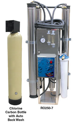
    Chlorine filters are essential to prevent chlorine from entering the membranes, as chlorine will cause rapid damage and failure. Additionally, a water softener is typically required to reduce water hardness to zero before it enters the membranes. When newly installed, the membranes take TDS down to zero.


    How Often Should You Change Your RO Membranes?

    Generally, RO membranes can last up to about 1 to 5 years, but the exact lifespan depends more on system usage and water quality than on time alone. Rather than focusing on a specific timeframe, it’s best to monitor the Total Dissolved Solids (TDS) level in the water your system produces. When TDS levels start to rise, it indicates that the membrane is less effective and may need replacing. This approach helps you avoid unnecessary changes while ensuring optimal water quality.

    Here are some key considerations to help you determine the optimal time to replace your membranes:

    Water Quality and Pre-Treatment

    • The quality of your incoming water greatly affects the lifespan of the membrane. High levels of water hardness, iron, or chlorine will greatly affect membrane life. If your water supply has high levels of these contaminants, you will likely need to replace membranes more frequently.
    • Pre-treatment options, such as sediment filters, carbon filters, and water softeners are very important for extending membrane life by reducing the burden on the RO membrane. 

    You can contact our sales team for help selecting pre-treatment options.

    System Usage

    • The more frequently your RO system is used, the faster the membrane will become filled with contaminants, and performance will go down. For car wash operations with heavy daily usage, you may need to replace the membrane more frequently.
    • In contrast, for systems used less frequently or with lower output, a membrane will last much longer.

    Regular Monitoring and Maintenance

    Performing weekly TDS checks is a key to monitoring the condition of your RO membrane. A handheld TDS meter can help you measure the TDS levels in the permeate (filtered water). If TDS readings exceed 40 ppm, it’s time to replace the membrane, as spotting generally occurs at this reading and above.

    Regular maintenance and monitoring can help catch issues early, preventing costly replacements and downtime. Cleaning the inlet filter and solenoid can prevent strain on the membrane. Your water softener should also be backflushed periodically. Many systems have an automatic backflush feature that cleans the filter media by flushing out accumulated contaminants, dirt, and debris, helping maintain the filter’s efficiency and lifespan.


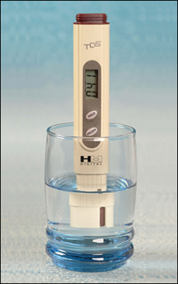
    Testing the TDS with a Handheld Meter

    Step-by-Step Instructions for Testing TDS with a Handheld Meter

    1. Prepare a Clean Sample Container:
      • Collect a cup or use the cap of the meter to hold your water sample.
      • Rinse the container thoroughly to ensure it is free of any contaminants.
    2. Collect the Water Sample:
      • Use the container to collect a sample of the permeate (filtered water) from your RO (Reverse Osmosis) system.
    3. Turn on the TDS Meter:
      • Remove the cap from the TDS meter.
      • Press the ON button to activate the meter.
    4. Insert the Meter into the Sample:
      • Place the TDS meter into the water sample up to the “ribbed” section on the meter for an accurate test (see image below).
    5. Swirl the Meter:
      • Gently swirl the TDS meter in the water for about 10 seconds to ensure the water flows consistently around the sensor.
    6. Hold the Reading:
      • Press the HOLD button on the meter to lock in the reading. This will allow you to remove the meter from the water without losing the result.
    7. Read and Record the TDS Level:
      • Check the TDS level displayed on the screen in parts per million (ppm).
      • The meter will hold this reading for approximately 20 seconds, giving you time to record the result.


    Dultmeier Item #HMTDS4


    Signs It’s Time to Replace Your RO Membrane

    Apart from monitoring TDS, there are additional signs that indicate it may be time for a new membrane:

    • High TDS Levels: If TDS readings start to increase rapidly or are above 40 ppm despite cleaning or flushing the system, this is a clear indicator that the membrane is no longer effective.
    • Decreased Water Production: A significant reduction in the system’s output or water flow could mean that the membrane is fouling or needing service.
    • Visible Spotting on Vehicles: For car wash systems, if you notice water spots on vehicles after washing, this suggests that the membrane isn't producing spot-free water.
    • Increased RO System Noise: An underperforming pump or noisy operation could indicate that the membrane is placing too much strain on the system.

    RO systems are complex and you can find more details in our guide to RO system troubleshooting.


    Recommended Tools and Equipment for RO System Maintenance

    To keep your RO system running smoothly, equip yourself with the following tools and replacement parts:

    Replacement RO Membranes

    Choose the right membrane based on your system’s specifications. Dultmeier offers a selection of RO membranes from several different manufacturers and systems.   

    TDS Meters

    Handheld TDS meters are essential for regular monitoring. You can use these to quickly check if your membrane is maintaining water at the appropriate quality standards.

    Pre-Treatment Filters


    Best Practices for Extending RO Membrane Life

    Perform Regular Maintenance

    Schedule routine checks on the prefilter, membrane, pump, softener, and carbon bottle. Replacing prefilters regularly will reduce the load on the membrane, ensuring it lasts longer.

    Flush the System Periodically

    Run a flush cycle to remove accumulated debris and scale from the membrane. This should be done according to your system's maintenance schedule or as needed based on water quality.

    Dultmeier offers RO systems with automatic flush mode, you can learn more about these systems here.  

    Invest in High-Quality Pre-Treatment Solutions

    Adding carbon filters, sediment filters, or water softeners will help protect your membrane from harmful contaminants and extend its service life.

    Monitor Water Quality Weekly

    Using TDS meters for regular monitoring helps you detect when the membrane begins to deteriorate. By staying ahead of TDS increases, you can replace the membrane before it causes major issues.


    Conclusion

    Changing your RO membrane every 1 to 5 years is a general guideline, but regular monitoring and maintenance play a critical role in determining the actual replacement schedule. By keeping a close eye on TDS levels, addressing any performance drops, and using quality replacement parts and pre-treatment equipment, you can maximize the efficiency and lifespan of your RO system.

    Sprayer Operations: Manual vs Automatic Rate Control

    When it comes to sprayers, planters, and other liquid application equipment, choosing between automatic and manual rate control is one major aspect that has a massive impact on the convenience and efficiency of your system. Each option offers advantages depending on your operation's needs, equipment, and budget. This blog will break down the key differences between these systems, how each one works, and the pros and cons of both to help you make an informed choice between the two.


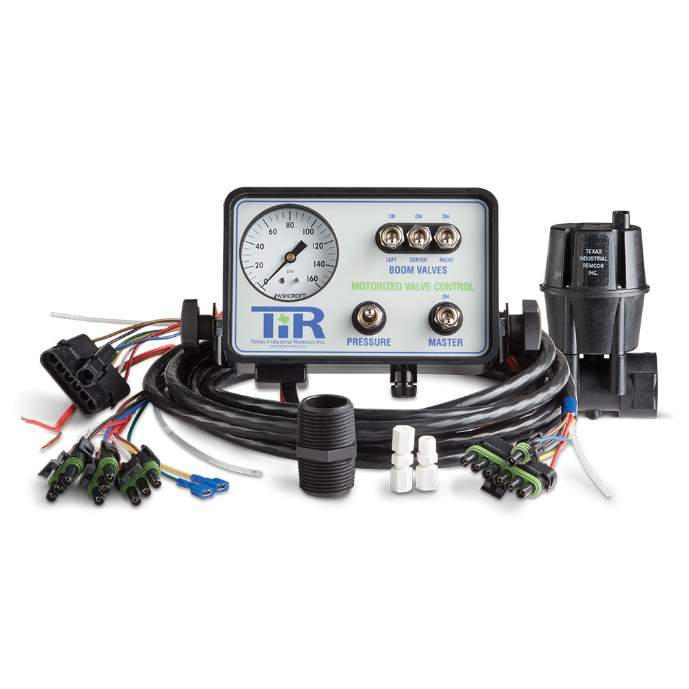
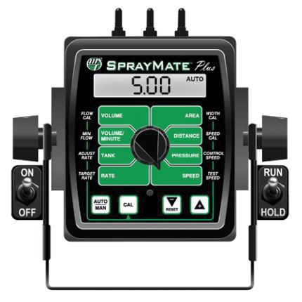
    Example of Common Sprayer Controls


    What is Rate Control?

    At its core, rate control refers to how the system manages the volume of liquid applied per acre. Precise control ensures that chemicals are applied at the correct rate, avoiding under-application that could harm yields or over-application that could waste inputs and increase costs.

    All rate control systems fit into two primary categories: manual and automatic control. The fundamental difference lies in how the system adjusts flow rates as ground speed changes. While automatic systems adjust the flow in real-time as you change speed, manual systems require you to adjust flow settings yourself. Let's dive deeper into each approach.


    Manual Rate Control: Simplicity at a Lower Cost

    Manual systems rely on the operator to adjust the application rate manually, either by changing the pressure in the system with a regulating valve or by controlling the speed of the pump motor/drive. This setup is typically much simpler and budget-friendly but requires more hands-on monitoring and manual adjustment during operation.

    manual sprayer rate controller

    How Manual Rate Control Works

    Manual rate control systems achieve the desired output primarily through two methods: varying pressure with a regulating valve or adjusting the speed of a pump motor/drive. Both approaches require hands-on operation and frequent adjustments to maintain accurate application rates.

    The first method involves varying pressure using a manual regulating or bypass valve. In this setup, the operator sets the system’s pressure to match the desired application rate. For example, you might calculate that at 5 mph, 28 PSI is needed to deliver 10 gallons per acre (GPA). However, if your speed increases to 6 mph, you must manually increase the pressure to 33 PSI to maintain the same 10 GPA (these numbers are just examples). This method demands careful pre-calculation of operating pressures for different speeds, along with frequent adjustments throughout the application process.

    The second approach involves using a mechanism to adjust the speed of the pump. Two common methods are using a rheostatic control to adjust the RPM of a 12-volt electric pump or a PWM valve to vary the flow of a hydraulic pump. These systems allow the operator to increase or decrease the pump’s speed to control flow rates. 

    While the flow can be adjusted in real-time, it still requires manual input based on changes in ground speed. If you speed up, you need to increase the pump RPM to keep the application rate consistent, and if you slow down, you must decrease the RPM to avoid over-application.

    For more details, you can examine the manual rate control plumbing diagrams here.


    Pros and Cons of Manual Rate Control

    Pros:

    • Lower upfront cost: Fewer components mean a more affordable setup.
    • Simplicity: Easier to install and maintain with fewer parts to troubleshoot.
    • Flexible with smaller operations: Suitable for fields where speed changes are minimal or predictable. Best option for skid sprayers or turf sprayers that utilize a spray gun rather than a boom. 

    Cons:

    • Labor-intensive: Requires constant monitoring and adjustment, which can be challenging when the operator has multiple things to monitor in the sprayer/tractor cab.
    • Inconsistent applications: Greater risk of  over- or under-application due to human error  
    • Less efficient: Not ideal for operations where speed frequently changes, like irregular terrain or fields with obstacles. Not ideal for prescription applications. 

    You can see more information about setting up simple and cost-effective manual rate control in this article about planter fertilizer systems.


    Automatic Rate Control: Precision and Convenience

    Unlike manual rate control systems where the operator constantly must monitor speed and adjust as best they can to changes in the field, automatic rate control systems take the guesswork out of fertilizer and chemical applications. These systems are designed to automatically adjust flow rates as ground speed changes. This type of control is especially necessary in larger operations requiring maximum efficiency.


    automatic rate controller


    How Automatic Rate Control Works

    Automatic rate control systems rely on sensors, controllers, and flow meters to monitor both ground speed and flow rate in real-time. As the system detects changes in speed—whether from variations in terrain or adjustments made by the operator—it automatically adjusts an electronic regulating valve (or PWM valve/motor) to maintain a consistent application rate, typically measured in gallons per acre (GPA).

    These systems remove the need for manual input during the application, which frees up the operator to check for plugged nozzles, monitor wind conditions, and obviously steer. Many automatic rate control systems are integrated with GPS or in-cab monitors to enhance precision further. 

    If you want more information then check out our article on the components needed for automatic rate control on a sprayer. 

    Pros and Cons of Automatic Rate Control

    Pros:

    • Highly accurate applications: Reduces waste and ensures nutrients or chemicals are applied at the correct rate across the entire field.
    • Increased efficiency: Operators can focus on other aspects of operation instead of manually adjusting settings.
    • Ideal for large-scale operations: Handles varying speeds and field conditions seamlessly.

    Cons:

    • Higher cost: Advanced components like sensors, monitors, and GPS integration increase the upfront investment.
    • More complex setup: May require professional installation and calibration
    • Potential for downtime: Malfunctioning sensors or controllers can be more difficult to troubleshoot and halt operations until repaired.


    Conclusion: Which System is Right for You?

    Choosing between manual and automatic rate control depends on the specific needs of your operation. Manual systems offer a cost-effective solution for small farms, acreages, pastures, sports fields, etc. Basically, anywhere you can maintain a fairly constant speed on level terrain. On the other hand, automatic systems are ideal for large-scale or precision farming operations where efficiency and accuracy are paramount, though these systems come with higher upfront costs and more complex maintenance.

    No matter which route you choose, Dultmeier Sales can help you identify the system that will meet your needs. Give us a call today and we’ll happily help you determine the best option for your operation.

    ⇒ Browse the Different Rate Control Options Available At Dultmeier Sales


    Shane Blomendahl, Author

    Tech Ag & Industrial Sales

    Shane Blomendahl is a tech sales veteran at Dultmeier Sales with over 10+ years of experience in liquid handling products covering several industries and applications.

    Learn More About Author