Search
Call for Live Order Assistance & Technical Support (7:30am-5pm CST)
All Categories
    Menu Close
    RSS

    Blog posts tagged with 'agriculture'

    (0) Ag Chemical Mixing System: Handling Mini-Bulk Chemical Without 12-Volt Pumps

    Chemical mixing is a crucial part of agricultural spraying. Regardless of the type of herbicide, fertilizer, or biologic you use, effective mixing requires proper equipment to ensure precision, safety, and minimize waste.

    The main tool to add mini-bulk chemicals is typically a 12-volt diaphragm pump and electronic meter. However, what if I told you there was a way to mix all your bulk chemicals without multiple 12-volt pumps? Let’s look at the pros and cons of the different options and explain how you can use one pump and meter for multiple products without recalibration or disconnecting and connecting hoses.

    Chemical Mixing With 12-Volt Pump and Meters: The Good and the Bad 

    Anyone mixing chemical batches for a sprayer is likely familiar with 12-volt chemical pumps and meters. These are necessary to add products to your sprayer batches either directly or through an inductor cone. These pumps are effective, but they have several drawbacks including maintenance, limited flow, and of course cost. 

    This method also limits your efficiency because you must calibrate multiple meters and add product one at a time carefully watching the meter until you have added your desired amount. You must shut off the valve, and pump, and then move on to the next product. There is also the constant handling of the hoses and meters, moving them around as needed, which can get messy. 

    More sophisticated systems, such as the Dura Auto Batch System, allow you to inject each product directly, eliminating the need to handle each one. They will even allow you to set the amount of product you want and automatically shut off the pump once that amount has been reached. 
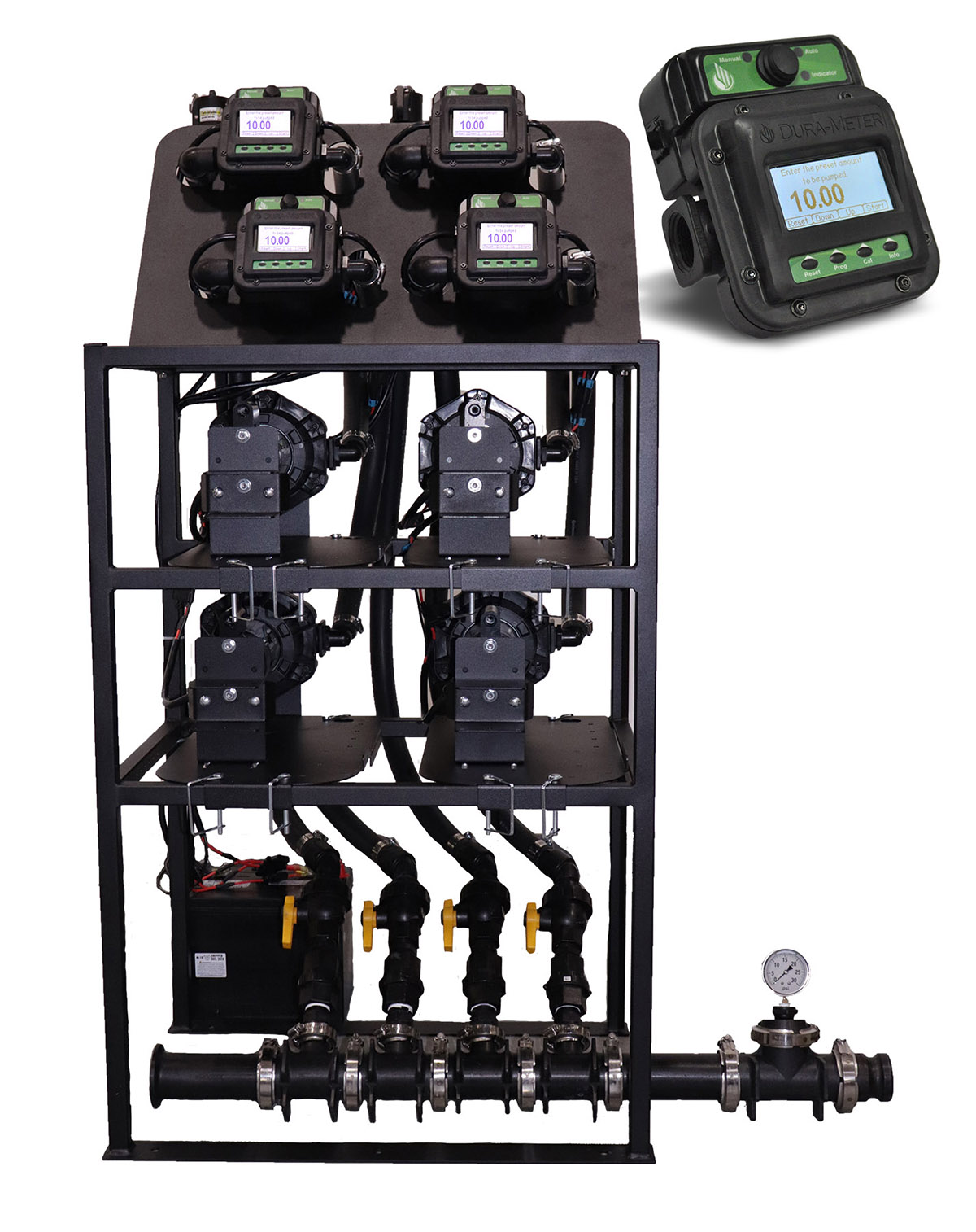


    This method definitely works well, and it is much more efficient. However, it does come with added cost and you still have the potential for pump and meter failure due to the nature of handling agrochemicals. 

    There are also automated systems to mix your chemicals without 12-volt pumps and meters. These provide the most streamlined option but they are by far the most expensive. The idea of being able to efficiently add chemicals while accurately measuring them without multiple 12-volt pumps and meters is certainly appealing, but how can you accomplish this without spending thousands if not tens of thousands?  

    The good news is that with the right transfer pump for the carrier liquid, meter, and inductor setup, this can be done!


    Ag Chemical Mixing Setup Without 12-Volt Pumps

    How exactly will one pump handle all the chemicals or additives? Instead of a 12-volt pump on each chemical tote, you can use the suction from a Venturi/inductor to pull product from each tote. This is the same type of inductor assembly that you would find under a cone bottom tank. (If you are not familiar with inductor tanks with a venturi, our guide on chemical inductors will get you up to speed.) 


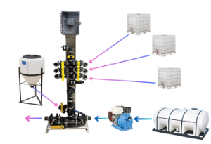
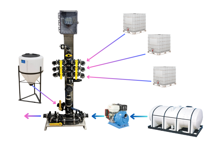
    In the following setup, instead of a cone bottom tank, we have a manifold stacked on top of a gear meter that can measure each product accurately. Each product is drawn into the manifold and through the meter, then feeds into your main carrier line into the sprayer or nurse tank. 
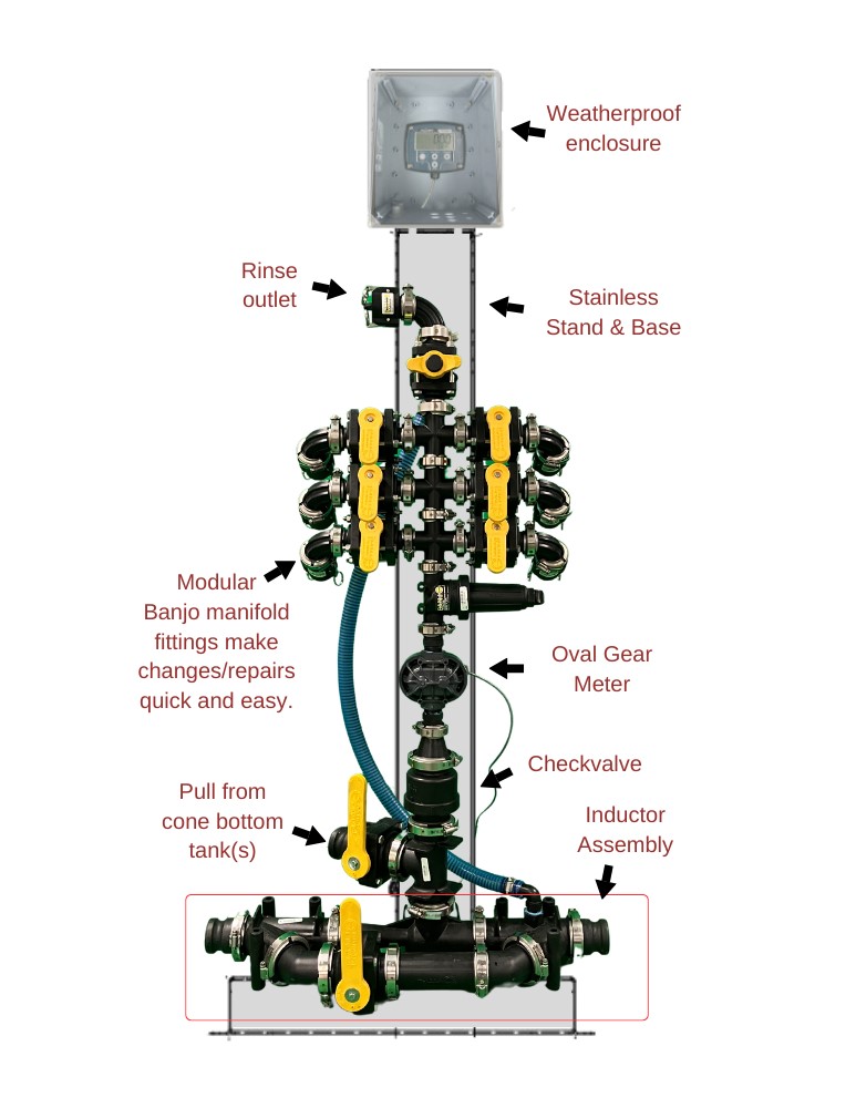
    Dultmeier quick chemical mixing system

    Everything is plumbed together allowing you to add each chemical one at a time. You simply open the corresponding ball valve for the product you want to add and watch the flow meter display until the desired volume is reached. Then close the valve, open the rinse valve to flush the system, and reset the meter before moving on to the next product.

    There are a couple of important aspects of this setup that make it work: 1) the gear meter handles all the chemicals without the need for recalibration, and 2) suction is needed to pull chemical from each tank. 

    The meter is pretty straightforward, you must ensure you are using a meter that can handle the different agrochemical viscosities. For this, an oval gear meter is required. It is the suction aspect that gets a little more tricky. 

    There are two distinct ways one can generate the required suction: You can use the suction from your transfer pump (typically a 2 or 3-inch gas-engine driven pump) or you can use suction from an inductor. These two methods can effectively be used to move your bulk chemical but there are key plumbing differences for each one. 

    Dultmeier sales offer prebuilt units that work with either method. We will examine those later in this article, but first, let’s walk through the differences between each one and consider the pros and cons of each.

    Option #1: Using Suction of Your Transfer Pump

    The simpler of the two methods is to use the suction created by your transfer pump. The pump is installed in your main carrier/water line. Each hose from your mini-bulk tanks is plumbed into a manifold. The outlet of the manifold is connected via a “T” fitting into your carrier line. All of the liquid, chemical, and water, is pulled through the pump and into the sprayer or nurse tank.
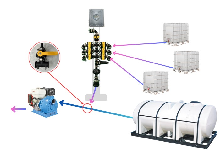
    ag chemical mixing using pump suction

    *Using the suction of a centrifugal pump to pull chemicals from the shuttle/mini-bulk tanks.


    Required Components

    • 2-inch or 3-inch Engine driven Centrifugal Pump (Preferably a “Wet Seal” Pump)
    • Oval Gear Meter
    • Flow Meter Display
    • Poly “Tee” Fittings for manifold
    • Ball Valves
    • Hose
    • Check valve

    Advantages of using suction from your pump

    • Lower overall cost
    • Simple to setup
    • Amount of chemicals you can add is not limited by the volume of the carrier that is pumped

    Disadvantages of using suction from the pump

    • All the chemical goes through the pump, potentially causing pump damage over time
    • Potential to introduce air in the pump or starve the pump of liquid, resulting in seal failure
    • Cannot use the pump to provide fresh water for rinse


    Option #2: Using Venturi/Inductor System

    The second method to draw your chemical into your system with your transfer pump is to utilize a venturi. The pump pushes the water/carrier through the venturi and this creates suction that can pull chemicals from the mini-bulk tanks and into your manifold then through the venturi. In this setup, there is no chemical going through the pump. 

    The suction is created by the venturi and the venturi is located on the discharge side of the pump. The pump can also provide rinse water because it is just pumping fresh water and not chemicals. 

    This would be a great option if you are already using a cone bottom mixing tank with an inductor venturi manifold on the bottom. You can plumb your chemical manifold into the bottom of your existing inductor cone. This will allow you to use the inductor assembly to suck product out of the cone bottom tank or your chemical manifold. 
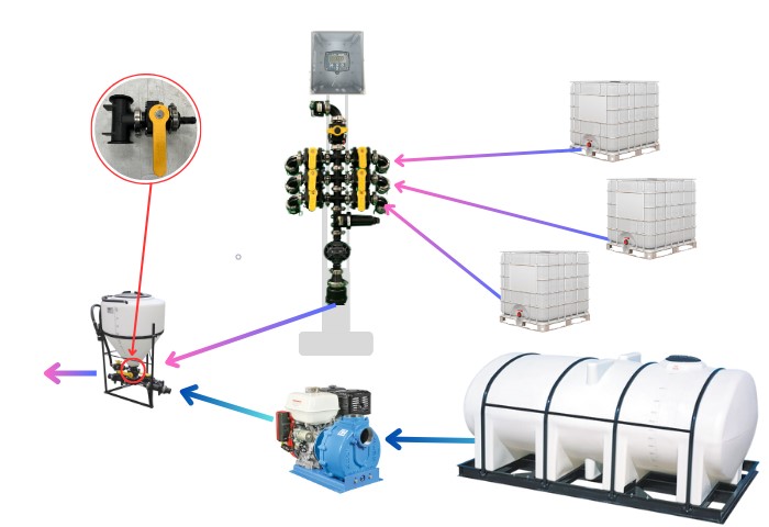
     

    *Using suction created from water pumped through inductor assembly to pull chemical from shuttle/mini-bulk tanks.


    Required Components

    • 2-inch or 3-inch Engine driven Centrifugal Pump (Preferably a “Wet Seal” Pump)
    • Inductor System with 2 or 3-inch Venturi Manifold
    • Oval Gear Meter
    • Flow Meter Display
    • Poly “Tee” Fittings for manifold
    • Ball Valves
    • Hose
    • Check valve

    Advantages of using inductor assembly for suction:

    • Only one pump is needed to create suction and provide rinse
    • No chemical through the transfer pump
    • No risk of starving the pump

    Disadvantages

    • More components required means more cost


    How to Construct Chemical Mixing Manifold

    The central feature of this setup is building your manifold so your transfer pump can be used to pull chemical into the system and meter it accurately. This means we need a “stack” of “tee” fittings on top of a meter with a freshwater line plumbed into the top. It is recommended that a strainer is installed prior to the meter to protect it from debris. 

    No matter which of these methods you choose, there are a few key aspects to keep in mind to ensure your system operates effectively. 

    Pump Type

    First off, the type of pump that you use matters. You can use a two- or three-inch pump. If your main carrier/water line is two inches, then use a two-inch pump. You need a three-inch pump if you want to use a three-inch line. It is important to ensure the pump has adequate horsepower to handle the demands of this application. Typically, this means 5 HP for a 2-inch pump and 9 or more HP for a 3-inch pump. Be sure to contact us if you need help identifying the right pump.

    This is especially important if you are using an inductor with venturi. Your pump must meet the flow rate requirements for the inductor assembly to perform adequately. A two-inch pump used with a three-inch venturi assembly will not generate enough flow through the venturi to create the suction needed to pull products out of the cage tank/mini-bulk tank. 

    Furthermore, it is recommended that you use a centrifugal transfer pump with a “wet seal”. This type of seal can be run dry for short periods of time without causing any damage to the seal assembly. This is especially significant If you plan to use the suction of the pump to pull product from each tote. You don’t want to risk damaging the pump if a tank runs empty and the pump starts pulling air. 

    Plumbing

    The hoses from the mini-bulk tanks/shuttles to the inlet of the manifold should be kept as short as possible. The suction of the pump is capable of pulling chemicals from about 20 feet with no problem but there is a limit. It is best practice to limit excess hose length, elbows, and other restrictions as much as possible so the system works efficiently. 

    Meter

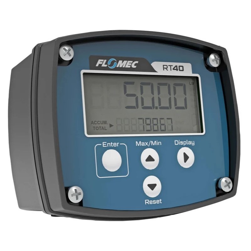
    Using one meter for all of your products requires a meter that does not need to be calibrated for each product and can handle liquids with different viscosities. An oval gear meter is capable of providing consistent measurements of flow rates for both high- and low-viscosity liquids

    You can use a meter with a local display to monitor the amount of chemical as it is added. This may be hard see because the meter is located on the bottom of the manifold. GPI offers a meter with a remote display option that can be mounted anywhere that is more convenient to see as you mix your chemicals.
     

    Check Valve

    A check valve is necessary to prevent any chemical or carrier flowing back into the manifold. This is installed between the meter and a “Tee” fitting in the main water line. 

    Manifold Flange Fittings

    Banjo manifold flange fittings are a style of plumbing connection that is much easier to work with than threaded fittings. These fittings are connected via a clamp and a gasket that provides a seal between the two flanges. Using these fittings saves a lot of time in the assembly and disassembly process. A single fitting can be isolated and removed/replaced without the need to unthread an entire group of fittings.

    Rinse 

    A feature that should not be overlooked. The rinse valve on the top of the manifold/stack ensures that all of the product is flushed out before adding another. The rinse line can be plumbed in a number of ways. The rinse plumbing will vary depending on whether you are using the pump suction or a venturi.

    If you are using the suction of the pump (without a venturi/inductor assembly), then you will require a second pump to supply fresh water to rinse out the system.


    Prebuilt Chemical Mix Unit: Quick Chem-Mix

    Assembling one of these units can be done fairly easily. You can configure it to work with your current chemical mixing station or sprayer nurse trailer. However, it does take a bit of time to build and wire the meter and display correctly. This is why Dultmeier offers ready-to-go systems. 

    The Dultmeier Quick Chem-Mix system (Part number DUCHEM-MIX) is a complete chemical mixing manifold, meter, and display plumbed together on a stainless steel stand. It can be easily incorporated into your nurse trailer or a stationary mixing location.

    There are two separate versions: with inductor assembly and without the inductor assembly. The full unit with venturi inductor (no tank) is ready to go, all you need is to install it on the discharge side of your transfer pump and connect your mini-bulk/shuttle tanks and you are ready to go:


    If you want to use it with an existing cone bottom tank and inductor you already have or use the suction of your pump, use the system without the inductor. You just connect the outlet to the inlet of your pump:
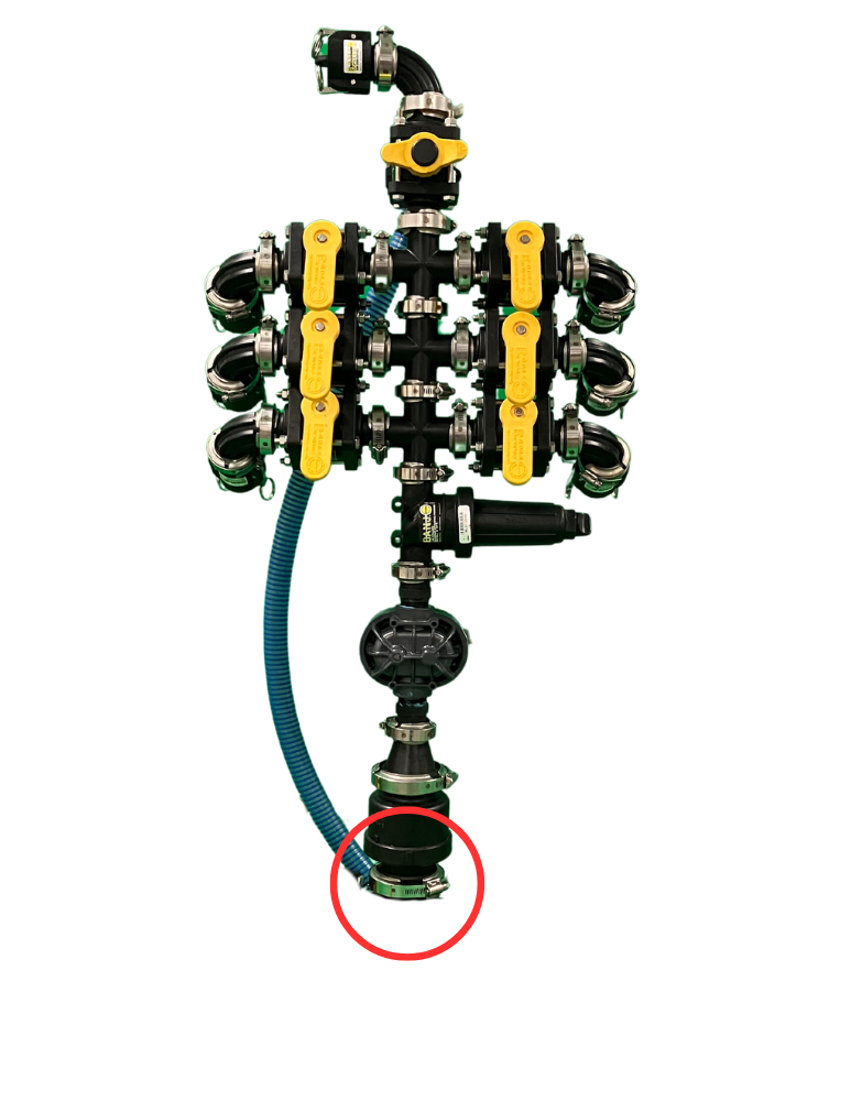
     

    Remember that the Quick Chem-Mix units without inductor will require you to plumb a separate freshwater rinse line to the manifold “stack”. 


    Quick Chem-Mix Benefits

    • Ability to pull chemicals from 20 feet or more depending on your setup
    • Meter up to six individual chemicals
    • One flowmeter for all products. There is no need to calibrate the meter for each product
    • The rinse feature ensures all product is flushed out of the manifold
    • Easy to plumb into existing inductor cones with minimal plumbing
    • No 12-Volt mini-bulk pumps, just a single transfer pump is needed
    • Available with 2 or 3-inch inductor assembly, also available without inductor assembly if you already have a cone bottom tank with inductor
    • NEMA-rated weatherproof enclosure protects the display 


    More Than One Way to Get the Job Done

    There are several effective options for mixing mini-bulk chemicals. The setup you choose depends on your preferences and budget. Whether you assemble it yourself or use the Quick Chem-Mix, this system offers an inexpensive way to conveniently mix multiple products without handling several chemical pumps and hoses. 

    If you prefer a more automated system be sure to check out the Dura Auto-Batch System

    Complete Guide to Planter Fertilizer Systems
    (0) Complete Guide to Planter Fertilizer Systems

    Corn, or any crop for that matter, requires nutrients to grow. In the pursuit of better yields the need for precise and timely application of these nutrients is almost as crucial as the type of nutrient itself. Accomplishing this often means applying liquid fertilizer even at the planting stage. 

    Accomplishing this requires a liquid delivery system on your planter. Today we are going to look at a variety of system options, explain their pros and cons, and determine what systems are best for a variety of scenarios.  

    Article Table of Contents - Click to Jump to a Section:


    Basic Planter Fertilizer System Overview

    For the purposes of this article, when we refer to different types of fertilizer systems, we are talking about the complete collection of equipment and devices used to deliver the liquid fertilizer. Including the pump, controls, hoses, valves, flow meters, etc. These systems vary widely in their complexity from the simpler systems with 12-volt pumps, to the more elaborate automatic systems with electronic flow monitors for each row. 

    Many Options to Choose From

    There are numerous options for each component of a planter fertilizer system because every operation has unique needs based on factors like fertilizer type, equipment, and budget.

    Putting a system together requires consideration of these factors and ultimately selecting the components that provide the features you want while remaining easy enough to install and operate. 


    Fertilizer System Overview

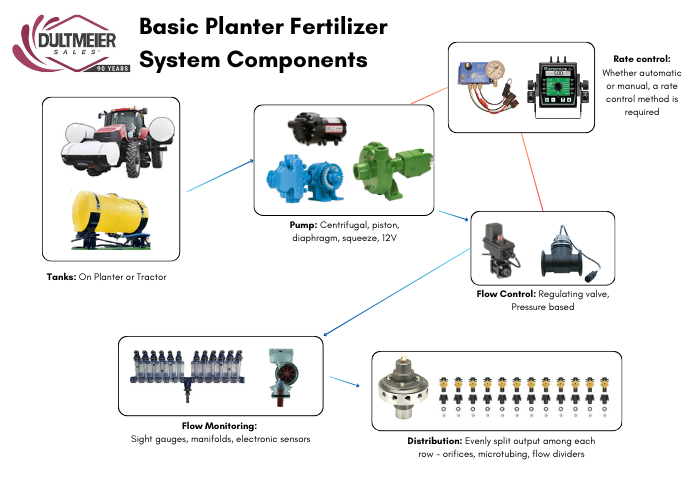
    We will get into more details about different types of systems in a moment, but first, let’s look at the basic layout of a fertilizer system. While different fertilizer methods (2X2, in-furrow, etc.) will require some slight variations, these basic components are going to be required in some form.


    Fertilizer System Diagram

    Fertilizer Tanks

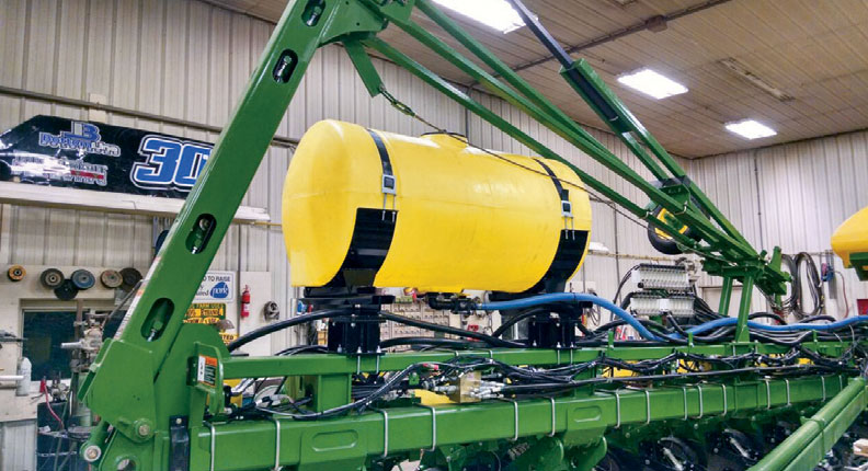
    Poly tanks are the go-to option for a wide range of fertilizers, agrochemicals, and soil biologics. Most tanks used in fertilizer delivery systems are either mounted on the planter or the tractor. No matter which setup you prefer, there are kits to accommodate several different planter makes/models as well as saddle tanks and helicopter tanks for tractors. 

    You can browse the various tank options here:

    Planter Fertilizer Tanks

    Tractor Tanks


    These kits make it pretty easy to identify a tank or set of tanks that will fit your equipment, but there are dozens of other tank sizes and shapes available if you are looking for something to fit a unique scenario. 


    Rate Control

    When it comes to controlling the system, there are two primary categories: automatic and manual control. Rate control refers to the mechanism used to change the volume of liquid applied. Simply put, you can opt for a system that automatically adjusts the flow as you speed up or slow down or one that requires you to manually make the adjustment. 

    Manual rate control systems are generally going to be simpler to use and less expensive. This also means, however, that they lack the convenience of automatic rate control systems. Typically, they do not accommodate prescription applications or data collection as an automatic system might. If you want more information, look at this comparison between auto and manual rate control


    Pump Type

    Pump type is another vital aspect to consider, and the main types used for fertilizer application are centrifugal, diaphragm, piston, and squeeze pumps. Here are the pros and cons of using each type:

    Pump Type

    Pros

    Cons

    Centrifugal High volume, easy maintenance, long service life (especially stainless steel), good for prescriptions Requires hydraulic outlets, cannot run dry (unless wet seal), more expensive, not self-priming
    Diaphragm Handles viscous products, self-priming, can run dry, higher-pressure capability, flexible installation Lower flow compared to centrifugal pumps, requires a pressure relief valve, and routine maintenance needed
    Piston Extremely accurate, durable construction, can prime from longer distances, ground drive models maintain application rate with speed changes Lower flow rate, not ideal for abrasive products, potential for pulsating flow from piston stroke
    Squeeze Simple setup, maintains rate with speed changes, stops when the planter stops, minimal additional components needed Less versatile, limited pump sizes and row configurations available
    12V Diaphragm Low cost, compact, easy to install, simple to operate, adjustable output with rheostat control Limited flow rate (3-6 GPM), not suitable for large planters, can overheat with continuous use or rapid stopping and starting


    For more details on each pump type, be sure to read our article about choosing the best fertilizer pump for your planter.


    Blockage Monitoring 

    Monitoring fertilizer applications is essential for efficient application. Accurate flow monitors help to prevent overuse that can harm plants and waste money. Monitoring systems detect clogs early, preventing missed application areas.  

    Just like with pumps and controls, there are blockage monitoring systems ranging from simple to more complex electronic meters.

    “Redball”/”VisaGage” Sight Gauges

    The most basic monitoring option is the liquid flow sight gauges also known as “Redball” monitors or “VisaGage” monitors. Several different companies make a version of these tools, but they all function the same.

    They consist of a series of clear vertical tubes, each corresponding to a specific row. As liquid flows through the system, colored indicator balls rise in the tubes, showing the flow rate for each row in real-time. If one ball is significantly lower or higher, it signals a potential issue that the operator can address.

    Flow monitors like Redball and VisaGage use color-coded balls with specific weights to indicate flow rate ranges. Lighter balls, suitable for low flow rates, require less pressure to lift, while heavier balls are designed for higher flow rates and pressures. Intermediate-weight balls cover medium ranges. The color coding allows operators to quickly and visually confirm the flow rate, simplifying monitoring and eliminating the need for manual measurements.

    Every brand offers their version of visual spray monitor variations to work with different pump types and system setups. There are manifold versions and squeeze pump versions, with threaded or push-to-connect ports. You can check out the various options available here:


    Electronic Flow Sensors

    In some instances, it can be hard to see the balls in the visual monitors due to the dark color of fertilizer or biological product. Unlike traditional visual flow columns, electronic flow monitor systems provide an audible alarm when a row is potentially blocked, ensuring operators can address problems quickly. Several electronic flow monitor systems exist that allow you to monitor all the rows on a console in the cab of the tractor:

    CDS-John Blue Liquid Blockage Monitors (LMBS)

    John Blue offers blockage monitor sensors that can be added to their visual monitors. These sensors have magnets that sense the ball inside the flow monitor columns, and when a ball drops below the desired range the system gives you a visual and audible indication on a display in the cab. 

     John Blue offers both a wired version with a simple display panel and a wireless version that can be paired with an iPad. The wireless iPad version provides a visual indication of the ball levels in each monitor while the simpler wired version only provides an indication if there is a block.

    Wilger Electronic Flowmeter (EFM)

    The Wilger EFM is an electronic flowmeter which installs in the liquid line of each row. The EFM uses a paddle wheel to measure the flow rate and sends a wireless signal to a tablet in the cab. Both color-coded visual indicators and audible alarms can be set to user preference for near-instantaneous monitoring of each row. The Wilger EFM system can monitor up to 196 separate rows, up to 10 sections, and can be easily retrofitted to your existing visual spray monitors. 

    Check out the Wilger EFM system here


    Distribution

    While major components like the tanks and pump may be the costliest items, your distribution system should not be overlooked. If you do not have the proper method to evenly divide the fertilizer over each row, your ROI will greatly decrease. 

    Flow dividers, orifices discs, and microtubing are all viable options, but how do you decide which one to use?  Well, the type of pump you use will ultimately determine which route you take. Let’s look at the primary methods of flow distribution and when to use them.  


    Orifices Discs

    Orifices are small stainless discs that control the flow rate by restricting the flow of liquid. Orifice discs are a simple and cost-effective distribution method which are typically used in 12V or centrifugal pump systems. They can be used as the nozzle or outlet and “dribble” fertilizer on the ground or installed inline ahead of a fertilizer rebounder or stainless tube.

    Orifices can also be installed on the top of the visual flow monitors (Redball). The benefit of this is less components down near the row unit that can get plugged up or potentially damaged. 


    *Stainless orifice disc and 18999EPR gasket installed in check valve nozzle bodies and cap.


    Microtubing

    One drawback of using orifice discs is that they are prone to plugging, especially when using products that have suspended solids in them.  , on the other hand, provides the same metering ability as an orifice with a larger fluid path, and this larger fluid path reduces the risk of blockages happening.

    Different size diameters of tubing correlate to different flow rates (GPM).  The tubing acts like an orifice, restricting the flow to deliver certain flow rates at various pressures. The difference is that the inside diameter of the tubing does not need to be as small as an orifice that provides the same relative flow rates because the friction loss of the fluid is extrapolated out over the entire length of tubing. In short, the fluid passes through a wider opening and has less risk of plugging while still delivering the same flow rates. 

    Microtubing is a great option with soil biologicals and really viscous fertilizers. You can check out the different Identifying the proper size requires doing some math, you can reach out to us for help. 


    Flow Dividers

    A flow divider is a device that splits the liquid that enters it evenly across each outlet. It is not simply a manifold; it is specially designed for even distribution. There is no need for orifices or additional metering as there would be with a basic manifold.  

    Flow dividers are used with ground-drive piston pumps. The total rate you want to apply per acre is set on the pump. Whatever the incoming flow rate from the pump, the divider splits it up accurately.

    Explore John Blue Flow Dividers


    Fertilizer Placement

    Getting the fertilizer delivered to the desired target is vital. In many cases, the fertilizer is simply dribbled on the ground but there are specific tools for in-furrow/pop-up and 2x2 applications. Totally Tubular stainless steel placement tubes are precision-engineered for several planter models and will allow you to apply fertilizer efficiently.


    Planter Fertilizer Setup Examples

    12-Volt Pump Fertilizer Systems

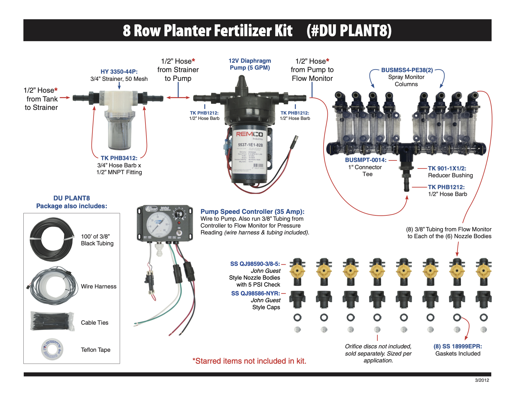
    Building your planter fertilizer system around a 12V pump is a low-cost, simple option. The basic setup would include the pump, pump speed controller, flow gauges, check valves, and orifice discs. In addition to these pieces, you will also need hose, fittings, zip ties, etc. 

    Here is what this complete setup looks like: 

    Dultmeier offers pre-boxed kits that contain components for 6-, 8-, 12-, and 16-row planters. These kits can also be customized for drills or planters with any number of rows or dual product placement needs. You can also easily upgrade from the basic sight gauge monitors to electronic flow monitors if desired.  You can see all the options


    12-Volt Fertilizer Pump System Pros 

    • Low cost
    • Simple to setup
    • Simple to troubleshoot

    12-Volt Fertilizer Pump System Cons

    • 12V pumps not a long-term option as the motors and internals tend to wear out sooner compared to other pump types.
    • Rapid pump cycling can lead to overheating
    • Limited to about 5 gallons per minute flow rates


    A 12-volt pump system will typically be adequate for 5-10 gallons per acre on 12-row planters traveling up to about 5 mph. You can use this GPM calculator to help determine the flow rate you will need from your pump. If you need to apply a rate above 10 GPA or have a planter larger than 12 rows, a centrifugal pump may be the right choice for you. 

    You can replace the 12-volt pump in the above kit with a hydraulic-driven centrifugal pump and use all the same components except the speed controller. Instead of the speed controller, you will need a rate control console and regulating valve or a rate control console and pump equipped with a PWM motor. 


    Ground Drive Fertilizer Systems

    Another simple planter fertilizer option is to utilize a ground drive pump. It offers automatic rate adjustment because the pump is driven by a planter shaft or ground drive assembly, the speed of the pump changes in direct relation to the speed of the planter. This is accomplished without the need for a rate controller or other electronics. 

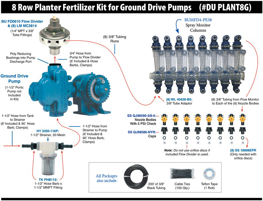
    In addition to the pump, the other key components are the flow divider and the spray monitor columns. As mentioned earlier in this article, a flow divider evenly splits the liquid among each row. Because the fluid is already divided, we don’t need the manifold-style flow monitors. Instead “squeeze pump” or independent columns with individual inlets and outlets are used to monitor the flow.

    Dultmeier offers all of these components in our “ground drive” planter kits to go along with a John Blue piston pump. The diagram below shows the layout of a ground drive fertilizer setup. Note that with a flow divider, there is no need for orifices downstream.


    Ground Drive Fertilizer Pump System Pros 

    • Simple to setup and troubleshoot
    • Higher flow rates than 12V systems
    • Automatic rate adjustment without electronics


    Ground Drive Fertilizer Pump System Cons

    • More expensive pumps
    • Gritty products or biologics with suspended solids may damage the pump


    Conclusion

    Choosing the right planter fertilizer system is crucial for maximizing crop yield and ensuring efficient nutrient application. By understanding the components—tanks, pumps, flow control systems, monitoring tools, and distribution methods—you can tailor a system to your operation’s specific needs, budget, and fertilizer type. The key is ensuring all components work harmoniously for precise and reliable application.

    For assistance in selecting or upgrading your system, Dultmeier offers a variety of solutions and expert support to help you achieve your goals.

    Sprayer Operations: Manual vs Automatic Rate Control

    When it comes to sprayers, planters, and other liquid application equipment, choosing between automatic and manual rate control is one major aspect that has a massive impact on the convenience and efficiency of your system. Each option offers advantages depending on your operation's needs, equipment, and budget. This blog will break down the key differences between these systems, how each one works, and the pros and cons of both to help you make an informed choice between the two.


    What is Rate Control?

    At its core, rate control refers to how the system manages the volume of liquid applied per acre. Precise control ensures that chemicals are applied at the correct rate, avoiding under-application that could harm yields or over-application that could waste inputs and increase costs.

    All rate control systems fit into two primary categories: manual and automatic control. The fundamental difference lies in how the system adjusts flow rates as ground speed changes. While automatic systems adjust the flow in real-time as you change speed, manual systems require you to adjust flow settings yourself. Let's dive deeper into each approach.


    Manual Rate Control: Simplicity at a Lower Cost

    Manual systems rely on the operator to adjust the application rate manually, either by changing the pressure in the system with a regulating valve or by controlling the speed of the pump motor/drive. This setup is typically much simpler and budget-friendly but requires more hands-on monitoring and manual adjustment during operation.

    manual sprayer rate controller

    How Manual Rate Control Works

    Manual rate control systems achieve the desired output primarily through two methods: varying pressure with a regulating valve or adjusting the speed of a pump motor/drive. Both approaches require hands-on operation and frequent adjustments to maintain accurate application rates.

    The first method involves varying pressure using a manual regulating or bypass valve. In this setup, the operator sets the system’s pressure to match the desired application rate. For example, you might calculate that at 5 mph, 28 PSI is needed to deliver 10 gallons per acre (GPA). However, if your speed increases to 6 mph, you must manually increase the pressure to 33 PSI to maintain the same 10 GPA (these numbers are just examples). This method demands careful pre-calculation of operating pressures for different speeds, along with frequent adjustments throughout the application process.

    The second approach involves using a mechanism to adjust the speed of the pump. Two common methods are using a rheostatic control to adjust the RPM of a 12-volt electric pump or a PWM valve to vary the flow of a hydraulic pump. These systems allow the operator to increase or decrease the pump’s speed to control flow rates. 

    While the flow can be adjusted in real-time, it still requires manual input based on changes in ground speed. If you speed up, you need to increase the pump RPM to keep the application rate consistent, and if you slow down, you must decrease the RPM to avoid over-application.

    For more details, you can examine the manual rate control plumbing diagrams here.


    Pros and Cons of Manual Rate Control

    Pros:

    • Lower upfront cost: Fewer components mean a more affordable setup.
    • Simplicity: Easier to install and maintain with fewer parts to troubleshoot.
    • Flexible with smaller operations: Suitable for fields where speed changes are minimal or predictable. Best option for skid sprayers or turf sprayers that utilize a spray gun rather than a boom. 

    Cons:

    • Labor-intensive: Requires constant monitoring and adjustment, which can be challenging when the operator has multiple things to monitor in the sprayer/tractor cab.
    • Inconsistent applications: Greater risk of  over- or under-application due to human error  
    • Less efficient: Not ideal for operations where speed frequently changes, like irregular terrain or fields with obstacles. Not ideal for prescription applications. 

    You can see more information about setting up simple and cost-effective manual rate control in this article about planter fertilizer systems.


    Automatic Rate Control: Precision and Convenience

    Unlike manual rate control systems where the operator constantly must monitor speed and adjust as best they can to changes in the field, automatic rate control systems take the guesswork out of fertilizer and chemical applications. These systems are designed to automatically adjust flow rates as ground speed changes. This type of control is especially necessary in larger operations requiring maximum efficiency.


    automatic rate controller


    How Automatic Rate Control Works

    Automatic rate control systems rely on sensors, controllers, and flow meters to monitor both ground speed and flow rate in real-time. As the system detects changes in speed—whether from variations in terrain or adjustments made by the operator—it automatically adjusts an electronic regulating valve (or PWM valve/motor) to maintain a consistent application rate, typically measured in gallons per acre (GPA).

    These systems remove the need for manual input during the application, which frees up the operator to check for plugged nozzles, monitor wind conditions, and obviously steer. Many automatic rate control systems are integrated with GPS or in-cab monitors to enhance precision further. 

    If you want more information then check out our article on the components needed for automatic rate control on a sprayer. 

    Pros and Cons of Automatic Rate Control

    Pros:

    • Highly accurate applications: Reduces waste and ensures nutrients or chemicals are applied at the correct rate across the entire field.
    • Increased efficiency: Operators can focus on other aspects of operation instead of manually adjusting settings.
    • Ideal for large-scale operations: Handles varying speeds and field conditions seamlessly.

    Cons:

    • Higher cost: Advanced components like sensors, monitors, and GPS integration increase the upfront investment.
    • More complex setup: May require professional installation and calibration
    • Potential for downtime: Malfunctioning sensors or controllers can be more difficult to troubleshoot and halt operations until repaired.


    Conclusion: Which System is Right for You?

    Choosing between manual and automatic rate control depends on the specific needs of your operation. Manual systems offer a cost-effective solution for small farms, acreages, pastures, sports fields, etc. Basically, anywhere you can maintain a fairly constant speed on level terrain. On the other hand, automatic systems are ideal for large-scale or precision farming operations where efficiency and accuracy are paramount, though these systems come with higher upfront costs and more complex maintenance.

    No matter which route you choose, Dultmeier Sales can help you identify the system that will meet your needs. Give us a call today and we’ll happily help you determine the best option for your operation.

    ⇒ Browse the Different Rate Control Options Available At Dultmeier Sales


    (0) High Volume Transfer: Discovering the Pump Types with the Highest Flow Rates

    Choosing the right pump can make all the difference in how smoothly your system runs, whether moving fertilizer, de-icing fluid, or pumping out a pit. One of the big questions people often ask is: which type of pump gives you the highest flow rate?

    The type of pump designed to produce the highest flow rate is a centrifugal pump. These pumps are intended to handle large volumes of liquid at relatively low pressures. They work by converting rotational kinetic energy, often from a motor, into energy in a moving fluid, which creates a flow rate that can be very high.

    If you're looking to move a lot of liquid quickly, the centrifugal pump is usually your best bet. Let's take a closer look at why these pumps are so good at handling large volumes with ease.


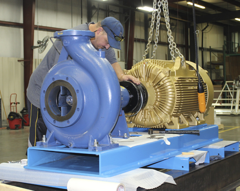
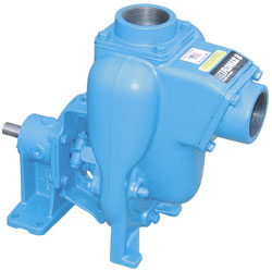
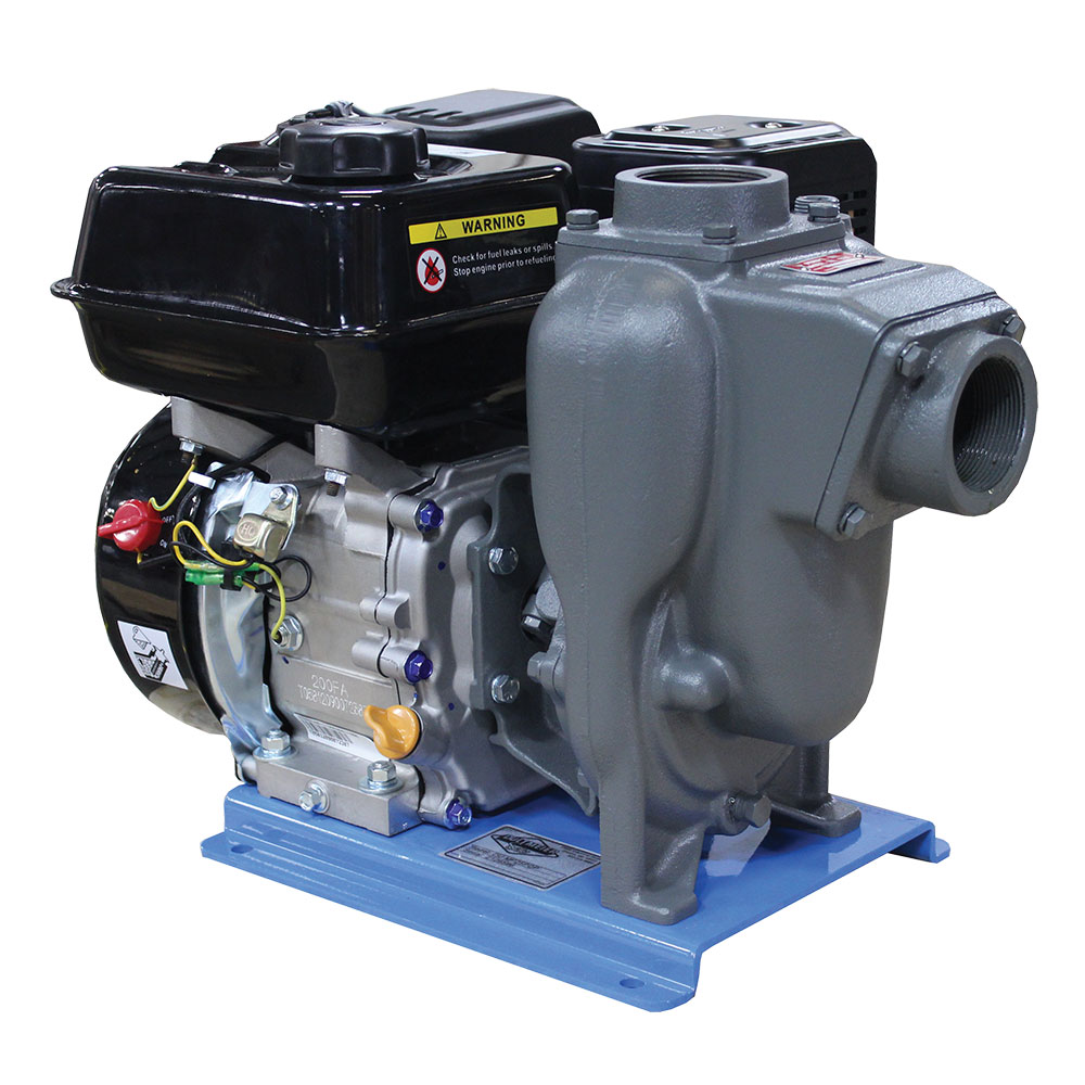
    Large Centrifugal Pump Unit


    Why Centrifugal Pumps Excel in High-Flow Rate Applications

    Centrifugal pumps are engineered to move as much liquid as possible in an efficient manner, making them the go-to choice when high flow rates are needed. Other pump types are designed to handle thicker liquids or to generate higher pressures, but a centrifugal pump's primary purpose is to transfer fluids that are relatively less viscous. Think water, fuels, fertilizers, and other flowable liquids.

    How Centrifugal Pumps Work

    Centrifugal pumps function by converting rotational energy into fluid flow, making them exceptionally efficient for high-volume transfer. You can read more on the specifics in our centrifugal pump guide. The short explanation is the heart of a centrifugal pump is the impeller. As the impeller spins, it imparts velocity to the fluid, pushing it outward from the center where the fluid enters, to the edges where it exits. This process creates a continuous, smooth flow of liquid.

    High Speed Equals High Flow

    The faster the impeller spins, the more kinetic energy is transferred to the fluid, resulting in a higher flow rate. This ability to maintain a steady, high-speed transfer of liquid makes centrifugal pumps ideal for applications that demand high flow rates.

    Continuous Flow for High Efficiency

    Unlike positive displacement pumps-such as gear pumps or piston pumps-that move liquid in cycles, centrifugal pumps deliver a continuous, non-pulsating flow. This is a significant advantage in applications where moving large volumes of liquid is essential, as it reduces turbulence and inefficiencies that can arise from intermittent flow. Because centrifugal pumps don't need to pause between cycles, they're more efficient for handling large volumes.

    Scalability

    One of the key benefits of centrifugal pumps is their scalability. These pumps can easily be adjusted to handle higher flow rates by increasing the impeller size or the speed at which the pump operates. This scalability is more straightforward compared to other types of pumps, where increasing the flow rate might involve more complex changes.

    High Flow at Lower Pressure

    Centrifugal pumps shine in applications where high flow rates are needed at relatively low pressures. While they might not be the best choice for high-pressure needs, their design is optimized to move large amounts of liquid with minimal energy input.


    Flow Rate Capabilities of Centrifugal Pumps

    The flow rate of a centrifugal pump can vary widely depending on the size of the pump, the speed of the impeller, and the specific design of the system. These pumps can achieve flow rates ranging from a few gallons per minute (GPM) to several thousand GPM. For instance, centrifugal pumps used in large-scale agriculture can easily move hundreds of gallons in a minute. 

    Common High-Flow Centrifugal Pump Applications

    Railcar Unloading

    Centrifugal pumps are ideal for transferring liquid fertilizer from railcars to storage tanks. In many scenarios flow rates of over 1000 gallons per minute are possible.

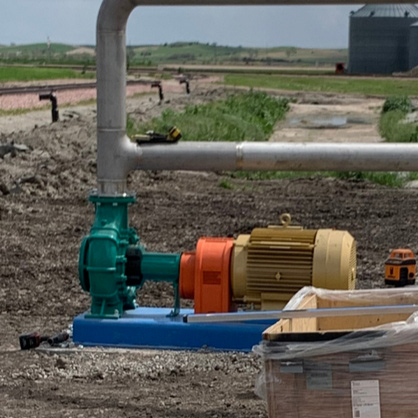
    High Volume Transfer Centrifugal Pumps

    Dewatering

    Centrifugal and submersible (a type of centrifugal pump) are ideal for moving water from construction sites, drainage pits, or any location where excess water accumulation could interfere with operations.

    Industrial Cooling

    In cooling towers, the volume of water that needs to be circulated is immense. Centrifugal pumps are ideal for this purpose due to their ability to handle high flow rates. These pumps ensure a continuous and reliable flow of water through the cooling tower.

    Industrial and Manufacturing Processes

    Centrifugal pumps are essential for the precise and reliable transfer of raw materials, intermediates, and finished products. Additionally, when precise flow control is needed, these pumps can be paired with variable frequency drives (VFDs) to adjust the flow rate accurately.

    You can read this beginner guide to sizing a centrifugal pump. Also, Dultmeier engineers have several combined years of experience sizing pumps according to the specific needs of several high-volume applications. Be sure to contact us if you have any questions.


    Factors Affecting Flow Rate

    Several factors affect the flow rate of a centrifugal pump, including:

    1. Pump Size: Larger pumps with bigger impellers can move more liquid per rotation, increasing the overall flow rate.
    2. Impeller Design: The shape and size of the impeller blades, along with the speed at which the impeller rotates, play a crucial role in determining the pump's efficiency and flow rate.
    3. System Head: The height and resistance the liquid must overcome (referred to as 'head') can impact the pump's performance. Centrifugal pumps are more efficient at lower heads, making them ideal for applications requiring high flow but not high pressure.

    If you would like a more detailed explanation of system head and flow rates, be sure to read our guide on centrifugal pumps written by in-house engineer Tom Hansen.


    Selecting the Right High-Flow Pump for Specific Applications

    Although a centrifugal pump is the best pump type for high-volume transfer of several fluids, in some scenarios a centrifugal pump may not be the best option. Thicker fluids may require a gear or diaphragm pump. Applications that require high-flow and higher pressures such as hydro excavating or sewer jetting, will need a different type of pump.

    Here are some common applications where a centrifugal pump may not be the best option and which pump types can offer the highest flow rate in each scenario:

    Tree Spraying: While a centrifugal pump offers enough volume, spraying tall trees requires more pressure than they can deliver. This is where high-flow diaphragm pumps come into play. They can deliver flow rates ranging from a few gallons per minute to over 100 while producing pressures from 250 psi and more.

    Liquid Feed Transfer: The combined viscosities and occasional cold temperatures of many liquid applications require a gear pump for high-volume transfer. Centrifugal pumps work in some scenarios but are limited when handling thicker, more viscous liquids like molasses.

    Learn more in our guide on how a gear pump works.

    NH3: Vane pumps are used for high-volume transfer of anhydrous ammonia. Centrifugal pumps can struggle with the low viscosity and high vapor pressure of NH3, leading to issues like cavitation, reduced efficiency, and potential pump damage.

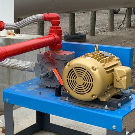
    High Volume NH3 Anhydrous Ammonia Pump Unit

    High-Pressure: Applications requiring higher pressures (think 1000 PSI+), and large volumes of fluid typically require plunger pumps or piston pumps. Pumps producing high-pressure and high flow rates do have significant horsepower requirements.

    12-Volt Power: 12-volt motor pumps are available for applications where only 12-volt power is available. The flow rates that can be achieved by these pumps are limited to a maximum of about 20-25 gallons per minute. This is only achieved at very low pressures, about 5 PSI. There are 12-volt pumps that produce 1-5 GPM at much higher pressures, typically 40-60 PSI, making them much more versatile for low-volume applications.


    Final Thought

    Centrifugal pumps are the top choice for high-flow applications, efficiently moving large volumes of low-viscosity fluids at lower pressures. Their scalability and continuous, smooth flow make them ideal for industries requiring reliable, high-volume liquid transfer.

    If you need help selecting and sizing a centrifugal pump you can reach out to our team. Our engineering department can provide flow analysis and expert guidance!

    Trash Pumps: Can I Use One to Pump Fertilizer?

    Resourceful folks are always looking for ways to get the most out of their equipment. One way to do this is to repurpose tools whenever possible. One such tool is the trash pump. If you already have one and need to move fertilizer, it only makes sense to wonder, "Can I use my trash pump for fertilizer?".

    The short answer is yes, in many cases, a trash pump can handle fertilizer. However, this is not always the case. Several factors affect a pump's ability to handle fertilizer, including the type of fertilizer, pump materials, horsepower, and more-all of which might impact the overall effectiveness and longevity of your trash pump.

    Do not worry. In this article, we will explore not only whether repurposing a trash pump for fertilizer is a feasible option but also which situations make the most sense. We'll cover the basics of trash pumps, the properties of fertilizers, and how to know if your specific pump can handle the job.


    What is a Trash Pump?

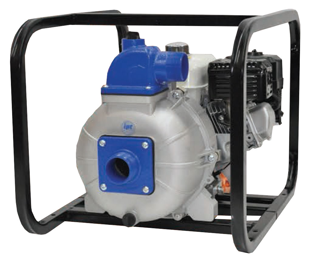
    A trash pump is a type of centrifugal pump that is designed to move water that contains large pieces of debris, such as sand, gravel, sticks, etc. Generally, they are self-priming pumps that are constructed out of. Some are made from more durable metals like cast iron or ductile iron, while less expensive models are aluminum or other alloys.

    Compared to other centrifugal pump types they are generally less efficient. This is because they are designed for versatility and not for efficiency. Most centrifugal pumps used for clear or "clean" fluids are more efficient because they have a smaller clearance between the impeller and the volute inside the pump housing.

    Trash pumps have a smaller impeller diameter in relation to the volute size, which allows them to pass rocks or other debris more easily without scoring the internals of the pump. This capability makes them particularly useful in construction, agricultural, and dewatering/drainage scenarios.


    Can Trash Pumps Handle Fertilizer?

    Fertilizers come in various forms: liquid, granular, and soluble powder. Each type has different handling and application requirements. Liquid fertilizers are often preferred for their ease of application and rapid absorption by plants. However, they can be corrosive or abrasive, depending on their chemical composition, which can include nitrogen, phosphorus, potassium, and various micronutrients in different chemical forms.

    The concept of using a trash pump for moving liquid fertilizer might seem viable. Trash pumps can handle slurries and fluids with solid particles, which theoretically could include liquid fertilizers. However, there are some things you need to consider, like material compatibility, efficiency, and reliability, before actually using your trash pump to transfer fertilizer.

    Trash Pump Chemical Compatibility

    Many trash pumps are designed to handle water and may not be compatible with the aggressive chemical nature of some fertilizers. Corrosion of the internal components, such as the impeller and the housing, can occur if the materials are not resistant to fertilizer chemicals.

    Materials Typically Not Suited for Common Liquid Fertilizers:

    • Aluminum
    • Brass
    • Polycarbonate
    • PVC

    Materials Recommended for Use with Liquid Fertilizer:

    • Cast Iron
    • Stainless Steel
    • Viton
    • Carbon Steel
    • Polypropylene

    In addition to pitting, rust, and corrosion of the housing and impeller, the pump seal can suffer damage from an aggressive fertilizer. Trash pumps typically have a mechanical shaft seal that keeps liquid from leaking out during operation. This seal consists of two faces and an elastomer that rub together to form a barrier.

    If the seal faces or elastomers are made from a material not compatible with the type of fertilizer you want to pump, the seal will fail. Abrasive fertilizers cause damage to the seal faces and the pump will leak around the shaft. This can happen gradually or quite quickly if the fertilizer and materials are not compatible.

    A fertilizer's with your pump materials might be the most crucial deciding factor for whether you can utilize a trash pump over another type of pump . If you are new to fertilizer transfer pumps, this guide explains in detail the different options for high-volume fertilizer transfer pumps.

    Trash Pump Efficiency

    Let's say your trash pump is constructed of materials that will stand up relatively well to whatever type of fertilizer you need to pump. Good, you can check off that consideration. However, there is still the matter of efficiency to consider. Trash pumps are by nature less efficient than other centrifugal pumps typically used for fertilizer transfer. You'll therefore want to ensure that your trash pump will actually perform as you need or you'll have to start at square one finding another solution.

    As mentioned earlier, trash pumps generally have more clearance inside them to pass solid material. This makes them less efficient. (If you want to fully understand centrifugal pump efficiency, then check our  You may be able to live with this lower efficiency, especially if it means not having to spend the extra money buying another more expensive pump.

    Even so, just because a trash pump may work, doesn't mean it will move the liquid at the same volume as other pumps designed specifically for the transfer of fertilizers. It's crucial then, that the prospective costs of that lower efficiency be weighed out for both the short-term and long-term benefits of your operation.


    Conclusion: Should You Use a Trash Pump for Fertilizer?

    While trash pumps are a versatile option in a pinch, there are better pumps available for the efficient transfer of fertilizer. Over a season the additional amount of time it takes you to move fertilizer could impact your bottom line. Not to mention trash pump built with metals not suited for your specific fertilizer could fail prematurely, costing you additional time and money than if you had opted for another pumping solution in the first place.

    Dultmeier carries several different pump lines that are well-equipped for fertilizer transfer:

    For more details on which fertilizer pump will work best for you, check out our guide on the best fertilizer pump options

    Chemical Inductors Guide: Keys to Efficient Operation

    Using a chemical inductor is an effective way to add chemicals into a mix load for a sprayer. At Dultmeier Sales, we assemble a variety of cone bottom inductor tanks with Venturi assemblies that ensure precise and efficient chemical mixing.

    In this article, we'll provide a complete guide on how chemical inductor systems work, covering everything from the principles behind the Venturi effect to the detailed operation of these systems. Whether you're new to using chemical inductors or looking to optimize your current setup, this guide will equip you with the knowledge you need.


    How a Chemical Inductor Works


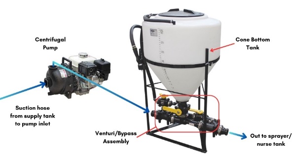
    The Venturi effect is the driving principle behind how a chemical inductor works. The Venturi effect occurs when a fluid flows through a narrow constriction, causing its velocity to increase and its pressure to decrease, creating a low-pressure zone that can generate suction. This happens in a chemical inductor when the carrier from the transfer pump flows into the inductor assembly on the bottom of the inductor tank.

    The suction effect draws the chemical from the inductor tank into the flowing water. As the chemical mixes with the water in the Venturi nozzle, the combined solution is then transferred into the main sprayer tank or nurse tank.

    This process not only requires a specific set of components but also the correct plumbing to work effectively. Let's examine each component and how they work together.


    Chemical Inductor Components

    Whether a chemical inductor system is on-board a sprayer, mounted on a tender trailer, or stationed on the ground, the core components are the same:

    • Venturi/bypass assembly
    • Cone bottom tank
    • Hose/plumbing
    • Centrifugal transfer pump


    Setup of a chemical inductor system.


    There are variations of each component depending on the specifics of the application.


    Venturi/bypass Assembly


    Chemical inductor system stand used for mixing chemicals in agricultural applications.


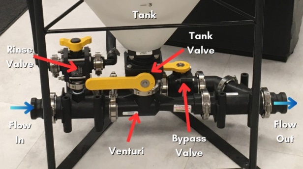
    The venturi bypass assembly is the critical piece of any chemical inductor system and essential to drawing in agrochemicals, AMS, crop oil, etc. into your final mix load. This assembly includes the venturi, bypass valve, and all appropriate plumbing fittings. When the bypass valve is closed water is forced through the venturi. Then the tank valve can be opened, and the contents of the inductor tank are drained by the suction from the venturi.

    When the bypass valve is open, water avoids the venturi and the flow rate is faster, but there is no suction to pull any mix of liquids or chemicals from the tank.

    If you are building a chemical inductor, you can add a venturi assembly to an existing cone bottom tank. You can also use a venturi/bypass assembly to pull chemicals directly into a carrier line without the cone bottom tank. For more information be sure to read this guide to mixing chemicals without 12-volt pumps


    Inductor Tank

    A cone-bottom polyethylene tank is recommended for use with agrochemicals (pesticides, herbicides, fertilizers, etc.) because it offers a wide range of chemical compatibilities. They are available in various sizes, commonly 15 to 110 gallons. The size of your inductor tank does NOT affect the rate at which chemicals are drawn into your mainline. A larger tank simply holds more product. The tank opening on the bottom of the tank, however, is important to consider. A smaller tank opening can restrict the induction rate and make your overall operation less efficient.

    The size of the tank lid also matters. For starters, a larger lid opening makes it easier to add chemicals and reduces the risk of spillage outside the inductor system. A larger 16-inch lid also allows you to use a Chem-blade jug emptying and rinsing system. With this accessory, you can quickly empty chemical jugs without opening them or pouring them.

    On this page, you can see all our available cone bottom inductor tanks.


    Plumbing/Hose

    Like the tank, it is recommended that the valves and fittings are also poly. Polypropylene not only works best with agrochemicals but is also suitable for other products such as salt-brine, fertilizers, acids, and cleaning solutions.

    EPDM rubber suction and discharge hoses, such as these offerings from Kanaflex (link) and TigerFlex (link) work great for the suction and discharge sides of your inductor system pump. Two- and three-inch hoses are common plumbing sizes used with inductors.


    Transfer Pump

    Although the pump is not an integrated part of the inductor assembly, it is a critical component required to make the system function. The inductor system must be used with a centrifugal transfer pump that is capable of pushing enough flow through the venturi to generate adequate suction. A general rule of thumb is to use a pump that matches the same size as your inductor's plumbing. So, use a two-inch pump with a two-inch inductor system, and a three-inch pump with a three-inch inductor system.

    Additionally, you'll need to ensure the pump has adequate horsepower to move the liquid through the inductor venturi. If the pump lacks enough horsepower, the pressure may be too low, which can limit the amount of suction created. For example, when pumping water, a two-inch pump with a five-horsepower gas engine will suffice for a two-inch inductor setup. If you have a three-inch inductor assembly, then you typically need a three-inch pump with 8+ horsepower.

    If your carrier is fertilizer or some other liquid heavier than water, you will likely need more horsepower to drive the pump. You can learn more about the pump sizes in our fertilizer transfer pump guide.


    Pump Options for Chemical Inductors:


    How to Install a Chemical Inductor System

    Like the pump, the plumbing setup of an inductor tank is crucial. The most important aspect is the placement of the pump in relation to the inductor system. The inductor should be positioned on the discharge side of the pump. This placement is essential because the flow of the water pumped through the venturi creates the vacuum effect.

    Using the right hose and fittings is vital to proper plumbing for inductor tanks. It is important to match the inside diameter of the hose and fittings with that of the pump ports. For example, a two-inch inductor system should have two-inch plumbing throughout. Hose, fittings, pumps, valves, venturi, etc., should also be two inches in diameter.

    Any restriction in flow can disrupt the system's effectiveness. Eliminating as many bends or slowdowns within your plumbing will ensure your flow rate remains strong enough to draw product down through the venturi. Try to limit the length of hose on the suction and discharge sides of the pump and avoid using too many 90-degree elbows and strainers.

    Furthermore, where you place your pump in relation to your system's water supply tank and inductor can affect the performance of the overall system. You will want to keep the pump as close to the water tank as possible, because the shorter the distance the water must travel to the pump, the less pressure loss you'll have and the better your pump will perform. Proper pump placement means a more reliable and effective chemical mixing process.

    Since plumbing plays such a large part in the overall performance of your inductor system, it's important to consider how every part of the system works in tandem with one another. As referenced above, the hoses throughout your system need to be the proper size to the inductor unit.

    This is also true for the pump inlet. A two-inch pump needs to be fed with at least a two-inch hose, a three-inch pump with a three-inch hose, and so on. You do not want to starve the pump or run it dry. This will result in seal failure in addition to the inductor not functioning properly.


    Chemical Inductor Plumbing Diagram

    Diagram of a chemical inductor system for agricultural mixing.

    Keys to Remember When Plumbing Your Inductor Tank:

    • Venturi Assembly: Must be on the discharge side of the pump.
    • Hose and Fittings: Match the inside diameter of your pump inlet and inductor.
    • Flow Optimization: Avoid 90-degree elbows and pumping great distances 100 ft +
    • Pump Placement: Keep the pump close to the supply tank for efficient operation.
    • Pump Operation: Never run the pump dry and ensure supply tank valves are fully open.

    Using an Inductor Tank Without a Venturi Assembly

    While most chemical inductors utilize a venturi assembly, you can use a cone-bottom tank without a venturi assembly by placing it on the suction side of the pump. However, this setup requires careful consideration to avoid starving the pump of liquid, which can cause pump cavitation and damage.

    One of the risks of positioning the inductor tank upstream of the pump is the possibility of air bubbles entering the system. When you open the tank valve, liquid in the tank is drawn into your carrier line, but you are also introducing air into the line. Air bubbles passing through the pump can lead to damage over time. A large amount of air can starve the pump and lead to seal failure rather quickly.

    Placing the inductor on the suction side of the pump also means you have chemicals passing through your pump rather than just water. Although many pumps are compatible with agrochemicals, this will inevitably lead to more wear and tear compared to water alone.

    You also have the risk of contaminating your water supply or water tank, though using a check valve between the water tank/supply and the cone bottom tank to prevent chemical backflow can likely eliminate this contamination risk.

    Conclusion

    When set up properly, inductor tank systems are a highly effective way to introduce multiple chemicals or fertilizers into your spraying application. Following these guidelines will help you build or improve your current set-up, ensuring efficient and reliable chemical induction for your sprayer.

    Dultmeier Sales offers a complete inductor system in poly and stainless steel as well as all the components needed to operate them:

    Inductor systems

    Pumps

    Hose

    Plumbing

    MP Pumps: Ag, Petroleum, & Industrial Fluid Transfer Solutions

    MP Pumps has been manufacturing quality centrifugal pumps for more than 80 years. Over this time, they have developed and improved upon their designs to offer reliable and affordable fluid-handling options for a variety of industries and applications.

    There is almost certainly an MP pump that will work for you, but sorting through the various types can be tough. As a master MP Pumps distributor, Dultmeier Sales can help you pinpoint the right one. Here's a detailed look at the different MP Pumps available, their common uses, and the advantages and disadvantages of each type.


    MP Pumps Company Overview

    MP Pumps has been around since 1942, proudly crafting high-quality centrifugal pumps from their home base in Fraser, Michigan. They've got a pump for just about everything from making sure your fertilizer and ag chemical system runs without a hitch to keeping industrial processes flowing smoothly, to moving petroleum products efficiently.


    MP Pumps Company Info:

    • Founding: 1942
    • Location: Fraser, Michigan.
    • Phone Number: (800) 563-8006
    • Parent Company: Ingersoll Rand
    • Website: MP Pumps


    Industries Covered:

    • Agriculture
    • Fuel
    • Transportation
    • Irrigation
    • Marine
    • Industrial


    MP Pump Types

    MP Pumps has an extensive product line. They manufacture self-priming pumps, straight centrifugal pumps, chemical pumps, circulator pumps, petroleum pumps, and more.

    Dultmeier Sales can supply just about any MP pump but we focus primarily on the ag, industrial, and petroleum pumps. These industries rely on the MP Flomax, Chemflo, and Petrolmaxx lines. One of the most common is the Flomax self-priming pump series, so let's start there.


    MP Flomax

    Description: These are self-priming centrifugal pumps. Available in materials like cast iron and stainless steel. Versatile, and capable of handling a wide variety of fluids. Many parts are interchangeable with other Flomax models.


    Common Uses: The MP Flomax pump can be implemented in countless situations. Dultmeier Sales has been selling the Flomax series pump for use in agriculture for several years. Specifically, nurse trailer and sprayer tender truck transfer pumps, as well as fertilizer and agrochemical bulk plant pumps. They are excellent at handling water, agrochemicals, and fertilizer but they can be used with other liquids as well.


    Key Features:

    • Capable of flows up to 750 GPM.
    • Handles pressures up to 230 head feet.
    • Stainless steel shaft sleeve for durability and corrosion resistance.
    • Self-Priming
    • Viton seals standard
    • Removable bolt-on FNPT flanges means your piping remains in place when servicing the pump
    • Wear plate can be replaced to extend the life of the pump
    • Suction check-valve holds liquid, protecting the pump seal when it re-primes

    Find Flomax Pumps Ready to Ship Today!


    Flomax Pump Options

    When it comes to connecting the pump to an engine or motor, MP offers the Flomax pump in two basic configurations. The pedestal version and the PumpPak version.


    Pedestal: A pedestal pump is designed to be long-coupled to motors, or other drives. It features a bearing pedestal and solid shaft.


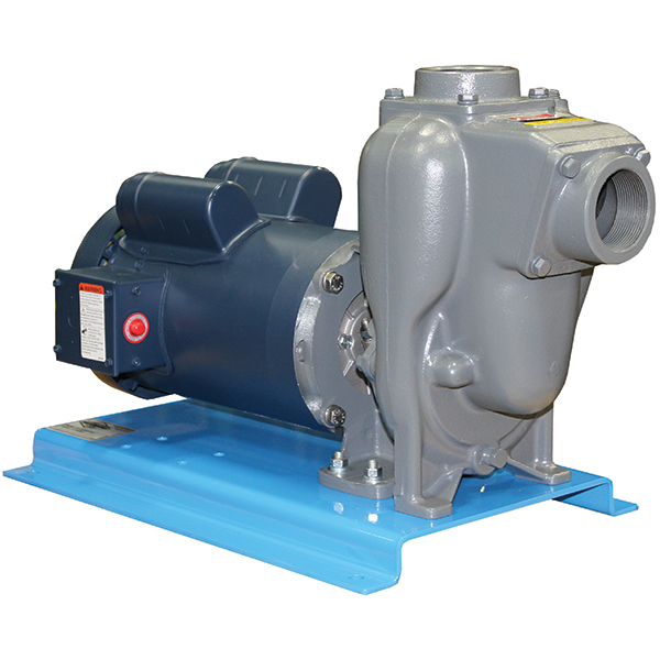
    MP Pumps 21339 Flomax 8 Pedestal Pump


    PumpPAK: This version of the Flomax pump is designed to be mounted directly to an engine or motor. There are versions to mount on gas-enines, hydraulic motors, and C-face electric motors.


    MP Pumps 21327 Flomax 8 pedestal pump


    Flomax Pump Sizes

    Flow rate is always key for any pump type. There are Flomax pumps made to deliver up to 750 GPM:

    • Flomax 5 - 1-1/2 inch ports, Up to 145 GPM
    • Flomax 8 - 2 inch ports, Up to 170 GPM
    • Flomax 10 - 2 inch ports, Up to 225 GPM
    • Flomax 15 - 3 inch ports, Up to 320 GPM
    • Flomax 30 - 3 inch ports, Up to 500 GPM
    • Flomax 40 - 4 inch ports, Up to 750 GPM

    Find Flomax Pumps Ready to Ship Today!


    Materials

    The Flomax line is available in several materials. Pumps constructed with cast iron housings and impellers, stainless shafts, and Viton seals are most common. All stainless pumps are available for more corrosive applications.


    Pump Drives

    An MP Flomax pump can be driven a number of ways. Whether you require an electric motor, engine, or hydraulic motor. The pedestal pump version can be assembled on a baseplate with motor and long-coupled together. The PumpPak version can be mated directly or close-coupled to C-face electric motors or gas engines.

    Various shaft sleeve sizes and bolt patterns are available so you can easily connect an MP pump to almost any C-face motor or gas engine.

    If you would like a more detailed explanation of close-coupled and long-coupled pump units, be sure to read this guide to the best fertilizer pump options.


    Chemflo Series

    Description: Some liquids are more harsh on pumps than others. The MP Chemflo stainless steel pump family is built to withstand more severe applications and corrosive liquids. There are several different variations within this family to be compatible with different types of liquids.

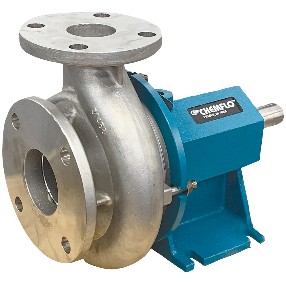
    MP CHEMFLO Centrifugal Pump

    Common Uses: Agricultural chemical mixing, fertilizer transfer, water treatment, de-icing liquids, and other industrial fluid transfer.

    Key Features:

    • Corrosion-resistant 316 stainless wetted components
    • Suitable for a wide range of chemicals
    • Available in a variety of sizes


    MP Chemflo Pump Options

    The Chemflo pump family is made up of more than 30 unique models. These different models are designed to be used in many different applications. They vary in flowrate, drive type, port size (flanged & NPT), etc.


    Sizes

    Chemflo pumps come in very low to high-flow options. Their CFX pumps have 1/2 to 1-inch ports with flow rates ranging from 10-40 GPM. The larger versions are available with 1-1/2 up to 3-inch ports and these pumps will provide maximum flow rates of 150-395 GPM.


    Materials

    One of the primary features of this pump series is the cast 316 stainless steel components used to construct the pump. While stainless is not an answer for 100% of liquids, it does offer resistance to the effects of a much wider range of liquids when compared to cast iron.

    While the housing, impeller, and other components are made from stainless steel, the mechanical seal is available with a variety of options including Viton, EPDM, and Teflon. You can always refer to our chemical compatibility charts to evaluate which materials and elastomers will be compatible with the liquid you need to pump.


    Drive Options

    Like other MP pumps, the Chemflo series comes in a variety of setups included long-coupled pump and motor units, close-coupled pump and motor units, and hydraulic-driven units.

    For more details and an explanation of close-coupled and long-coupled pump units, be sure to read this guide to the best fertilizer pump options.


    PetrolMaxx Series

    Description: Pumping fuels in high-volume applications requires the right type of pump for efficiency, compatibility, and safety. MP's PetrolMaxx series is a self-priming pump similar in design to the Flomax family but constructed with materials compatible with fuels. There are variations to ensure compatibility with diesel, biodiesel, gasoline, E85, and more.

    MP25POP PetrolMaxx Pump Unit

    Common Uses: High-volume fuel transfer. Loading and unloading bulk fuel trailers and trucks. Filling large equipment for construction and agriculture.

    Key Features:

    • Self-priming
    • Available to mate directly to engines/motors or with a bearing pedestal for long coupling
    • Flow rates of 150-700 GPM
    • Options for Ethanol, Biodiesel, Gasoline, Diesel, and More


    MP PetrolMaxx Options

    For safety and compatibility, it's crucial to use the right pump for each type of fuel. That's why MP has created a variety of pump models designed specifically for different fuels. Each model is built with materials that match the unique properties of the fuel it's meant to handle, ensuring safe and reliable operation.

    One of the most popular versions is made to handle diesel. Dultmeier sells hundreds of two-inch PetrolMaxx pumps driven by gas-engines for high-volume diesel fuel transfer. These pump units help fill equipment much faster than the common 12-volt fuel pumps. You can get flow rates well over 100 GPM with the right size hose and fuel filters.


    MP Petroleum Pump Sizes

    • 1-1/2 Inch
    • 2 x 2 Inch
    • 3 x 3 Inch
    • 4 x 3 Inch
    • 4 x 4 Inch

    See More MP PetrolMaxx Pump Options Here


    Materials

    As mentioned earlier, the PetrolMaxx family of pumps consists of several pumps fitted for specific fuels. The materials used include: steel, aluminum, cast iron, ductile iron, nitrile, 316 SS, Viton, Ni-resist, and more.


    Drive Options

    You can fit a PetrolMaxx pump to a gas-engine, electric motor, or hydraulic motor. It is important to note that some fuel types may require the use of an explosion-proof motor or gas-engine.

    Dultmeier sales builds pump units on baseplates for easy installation. The units are available close coupled to electric motors or engines, and long coupled to electric motors. There is also a complete fuel unit with a hose reel, pump, fuel filters, fuel nozzle, and base plate.


    MP Pump PetrolMaxx Gas Engine Driven Pump Unit

    View All Pump & Engine Units

    MP3010C Transfer Pump Unit

    View Pump & Electric Motor Units


    Final Thoughts

    MP Pumps has been a reliable supplier for years offering a wide range of pump solutions. Dultmeier sales has relied on MP as a competitively priced and durable pump for the rigors of the primary industries we have served. Including the fertilizer and ag chemical world as well as for de-icing, industrial, and fuel transfer.


    Shane Blomendahl, Author

    Tech Ag & Industrial Sales

    Shane Blomendahl is a tech sales veteran at Dultmeier Sales with over 10+ years of experience in liquid handling products covering several industries and applications.

    Learn More About Author

    A Comprehensive Guide to Pre-Season Preparation for Farmers: Maximizing Yield and Efficiency


    This guide focuses on the unique needs and challenges of row crop farming, emphasizing efficient use of resources, technology integration, and sustainable practices to enhance productivity and profitability.


    1. Soil Testing and Field Preparation

    Conduct Detailed Soil Tests: Test each field for pH, nutrient levels, and soil composition to guide precise fertilizer and lime applications. Soil sample analysis can be done by your local soil laboratory or extension service.

    Field Preparation: Implement tillage practices suited to your soil type and crop needs. Minimum tillage can preserve soil structure and moisture, while conventional tillage may be necessary in certain conditions to prepare a seedbed, control weeds, or incorporate amendments.


    2. Crop Selection and Rotation

    Select Adapted Varieties: Choose crop varieties with high yield potential, disease resistance, and adaptability to your climate. Consider traits such as drought tolerance or herbicide resistance as applicable.

    Implement Crop Rotation: Rotate crops to break pest and disease cycles, improve soil health, and optimize nutrient use. Plan rotations to include legumes to fix nitrogen, reducing the need for synthetic fertilizers.


    3. Seed Treatment and Planting

    Use Treated Seeds: Opt for seeds treated with fungicides and insecticides to protect against early-season pests and diseases. Consider seed treatments that enhance germination under cold or wet periods or seed varieties which tolerate drought or high-wind conditions.

    Precision Planting: Use precision planting equipment to ensure uniform seed depth and spacing. Calibrate planters for specific seed sizes and adjust planting rates based on germination tests and field conditions.


    4. Water Management

    Irrigation Efficiency: For irrigated fields, optimize irrigation schedules and methods (pivot, drip, or furrow) based on soil moisture monitoring and crop water needs. Consider technology like soil moisture sensors and weather-based irrigation scheduling.

    Drainage: Ensure proper field drainage to prevent waterlogging and enhance root development. Install or maintain drainage systems where necessary.


    5. Integrated Pest Management (IPM)

    Scouting and Monitoring: Regularly scout fields for pest and weed pressure. Use thresholds to make informed decisions about the need for interventions.

    Chemical and Biological Controls: Use targeted chemical controls when necessary and consider biological controls like beneficial insects for sustainable pest management.


    6. Machinery Maintenance and Calibration

    Equipment Readiness: Ensure all planting, tillage, and spraying equipment is in good working order before the season starts. Perform necessary maintenance and repairs during the off-season.

    Planter Calibration: Precisely calibrate planting equipment to match seed size, type, and desired planting rate. Check and adjust downforce, seed tubes, and closing wheels to ensure optimal seed placement. Perform a short test swath of planted seeds to ensure all settings are correct before planting entire fields.


    7. Technology in Farming

    Adopt Precision Agriculture: Utilize GPS-guided equipment for precise planting, fertilizing, and spraying. Consider variable rate technology (VRT) for applying inputs based on soil and yield data.

    Data Management: Use farm management software to track field operations, input applications, and crop performance. Analyze data to make informed decisions for future seasons.


    8. Weather and Climate Adaptation

    Weather Tracking: Use weather forecasts and climate data to plan field operations and mitigate risks from extreme weather events.

    Resilience Practices: Implement practices to increase crop resilience against climate variability, such as cover cropping, diversified cropping systems, and conservation tillage.


    9. Economic Planning and Risk Management

    Cost Analysis: Conduct detailed cost analyses for each crop, considering input costs, projected yields, and market trends.

    Risk Management: Utilize crop insurance and marketing strategies (futures, options, contracts) to manage price and yield risks.


    10. Professional Development and Networking

    Continuous Learning: Stay updated on agronomic research, crop protection products, and new technologies through extension services, agricultural publications, and professional associations.

    Collaboration: Engage with local farming groups, cooperatives, and research institutions for shared learning, market opportunities, and collaborative projects. 

    (0) Disinfectant Basics - 3 Methods for More Effective Disinfecting

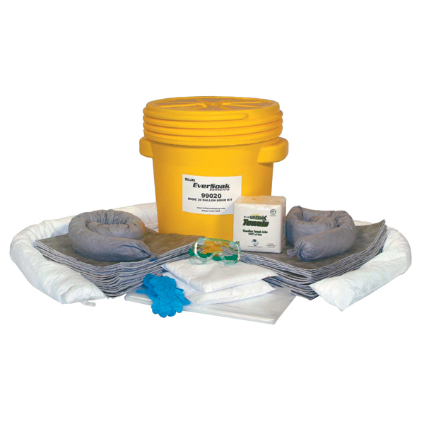
    20 Gallon Spill Kit

    We speak a lot about sanitation and disinfection these days. From the office and classroom to our own personal spaces, we are focused on cleaner, safer areas more than ever. And while many businesses are just now taking a closer look at how they clean their facilities, disinfecting in food processing has long been serious business. That doesn't mean all disinfectants for food processing cleaning are made equal.

    Disinfectants come in a variety of forms, each with its distinct advantages and disadvantages. In fact, which disinfectant you choose for your application is just as important as the why and how you disinfect. As we'll cover in this article, understanding the basics of each disinfectant type and the general rules behind applying them ensures a more comprehensive and cost-effective cleaning regimen. Read on for our breakdown of disinfection basics for more effective disinfecting.

    Why Disinfecting in Food Processing is So Important

    While commercial processing facilities spend the majority of their time up and running, their most important activity occurs when the production floor is empty and silent. Maintaining clean, sanitary workstations and equipment, particularly in food processing, is integral to public health and safety. In the United States, such standards are overseen by government agencies such as the EPA, CDC, and USDA.

    But why disinfect at all?

    E. coli, a common bacterial target of disinfecting food processing facilities

    E. coli, a common bacterial target of disinfecting food processing facilities


    Well, for starters, food processing plants are not the cleanest places once production gets going. Soils, in the form of fats, oils, blood, and other animal protein and production byproducts, quickly collect on equipment and surrounding surfaces. Such deposits, if left unaddressed, make these surface areas ideal breeding grounds for countless hosts of bacteria, viruses, and other potentially harmful microorganisms.

    Proper cleaning removes these unwanted soils and contaminants, providing significant benefits downstream. Maximized production efficiency, increased product shelf life, safer work conditions, and fewer mechanical failures and delays are but a few positive outcomes to attentive housekeeping. Scheduled cleaning and disinfection also significantly decrease the chances of costly product recalls due to food hazard risks such as food poisoning or foreign body contamination.

    A processing plant's commitment to a culture of health and food safety can easily be seen by how devoutly they approach the cleaning and disinfecting processes. And yes, there is a difference between the two.

    Cleaning vs. Disinfecting

    For most of us, cleaning, sanitizing, and disinfecting are all one and the same concept. They are, however, three distinct steps within the larger cleaning process. Cleaning is the process of physically removing unwanted substances and contaminants from a given surface. The cleaning stage, sometimes referred to as the detergent stage, is often characterized by the removal of common soils such as dirt, grease, or oils via manual scrubbing with brushes or wipes or washing with a high-pressure spray wand. Cleaning a surface in this manner alone; however, will not kill germs present.

    Tub-O-Towels - Heavy Duty Cleaning Wipes for removing difficult soils

    Heavy Duty Cleaning Wipes for removing difficult soils


    Disinfecting on the other hand, does kill bacteria and other microorganisms left behind following the cleaning stage. While similar to sanitizing agents, which merely reduce the number of bacteria and other germs to acceptable levels of health safety, surface disinfectants make a surface truly contaminant-free. Their high bactericide concentrations of chlorine or bleach eliminates the ideal growing conditions bacteria and other microorganisms thrive on.

    TACT Disinfection Cycle


    Every cleaning application will follow a distinct set of variables, generally known as TACT. The four aspects of this cleaning/disinfection concept are time, temperature, action, and concentration. How prominently each phase is in the disinfecting cycle depends specifically upon your unique needs, including the soils you're wanting to destroy, and the chemicals being used. Followed properly, the combination of them all will achieve the desired result of a clean, disinfected space.

    It's important to understand that cleaning must take place before the disinfecting stage. Since disinfectants do not break through heavy soils on surfaces, removing such deposits ahead of time ensures the disinfectants are able to work with the greatest efficacy.

    Choosing the Right Disinfectant for the Environment & Application

    Today, disinfectants cover a wide spectrum of chemical concentrations and applications. Choosing the right disinfectant for a specific environment, therefore, can be a task in and of itself. A few things to consider.
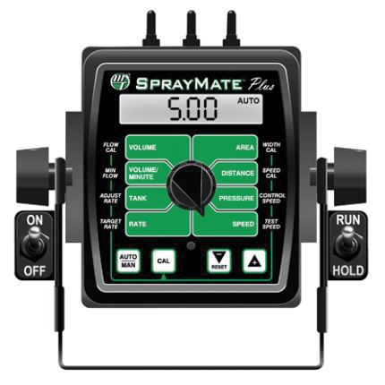
    First, the choice of disinfectants depends foremost on a user's requirements. In other words, where are they disinfecting and what type of contaminants are they trying to eliminate. After that, the type of processing and cleaning equipment used, the application method, and, to some degree, the personal preference of the user all play a role in selecting a disinfectant.

    Also, review a disinfectant's toxicity, leftover residues, and any possible chemical reactions related to water hardness and various surface types. This is particularly important within the food processing industry. Any residual chemical compounds left behind after disinfecting can adversely affect product taste, curing, and shelf life. In the brewing industry, for example, certain disinfectant cleaners are avoided because they linger on glass surfaces. (Soapy beer anyone?) Understanding a disinfectant's proper application process and any residue properties it has helps prevent product quality from suffering.

    Once a disinfectant is chosen, the most important thing to remember is to always read your disinfectant product labels! Always. With effective cleaning practices, disinfectants will kill 100% of germs listed by the label-when used properly.

    Disinfectant Label


    Ignoring what's detailed on the label-or choosing not to read it altogether-is a great way to undermine a disinfectant's effectiveness and cause mechanical failure of your disinfecting systems. It's also quite dangerous. Later in this article, we'll cover some of the safety considerations and equipment needed when dealing with disinfectants. For now, just remember that the label is the law. By following the label, you keep you, your cleaning staff, and anyone who comes in contact with the disinfected area, directly or indirectly, safe.

    Disinfectant Type Comparison: Foam, Spray & Steam

    Most of the food processing industry today relies on three common disinfectant application types: foam, spray (aerosol), and steam. Since no two environments are exactly alike, no two disinfectants will perform equally across the board either. Below we've provided some comparisons for these three disinfectant types and some general considerations to have before choosing the right disinfectant for your situation.

    Foam Disinfectants

    Foam Disinfectants


    Pros:

    • Better coverage of surfaces
    • Greater visibility of coverage
    • Lower pressure application
    • Less product needed to work
    • More cost-effective than other disinfectants

    Cons:

    • More challenging mix ratios
    • Added costs if needing separate surfactant agent
    • Greater attention to spray nozzle orifice size
    • Greater flow needed to apply

    Foam disinfectants are quite common in most food processing and industrial operations. Why? For starters, foam disinfectants can offer up to 50% more coverage than sprays. This is because foam expands as it comes in contact with a surface, greatly increasing coverage and disinfecting performance. In large production spaces, such as production floors or livestock barns, this helps keep cleaning costs down. Users can realize up to 50% cost savings on chemical alone, with additional savings possible in application time as well. Foaming is also a great option for disinfecting ceilings and vertical surfaces since the foam adheres better than sprays and therefore extends disinfection dwell time.

    One challenge with foam disinfectants, however, is the need to include a surfactant. A surfactant is a foaming agent that chemically reacts with your disinfectant chemicals. Surfactants also lower the surface tension between two materials, such as water and dirt, making the soil easier to remove. Without a surfactant, your disinfecting solution will not foam properly, making it less effective. While some disinfectants include a surfactant already, most do not. Be sure to read your labels prior to starting your cleaning process to ensure proper solution effectiveness.

    Additionally, check that your application equipment is compatible with foam solutions. Using a high-pressure pump without the appropriate chemically compatible elastomers is a great way to ruin an expensive pump. It is imperative, therefore, to check the chemical compatibility of ALL components throughout your entire cleaning systems. That includes examining the largest pump to the tiniest o-ring. In doing so, you not only avoid costly equipment damages or failures, but also prevent ineffective treatment from taking place.

    Hydro Systems FoamMaster


    Opt for chemical spray foamers and accessories that feature downstream injectors that bypass incompatible seals and components. Better still, invest in a complete foaming system like the Hydro FoamMaster. Available in multiple mounting styles, the FoamMaster is ideal for larger industrial cleaning applications, from washdown facilities and meatpacking plants to animal production buildings, such as the dairy barns shown in the video above. These compressed air units allow a user to set the desired dilution rate for their specific application. From there, the system mixes the chemical and surfactant with the carrier agent (generally water) to create rich, clinging foam.

    Dultmeier has even helped develop custom disinfecting systems. Check out our work on the JBI Poultry Disinfectant Foaming Trailer here.

    Spray Disinfectants

    User disinfecting with spray in an industrial kitchen

    User disinfecting with spray in an industrial kitchen


    Pros:

    • Fewer chemical compatibility issues
    • Quick-and-easy to apply
    • Wide variety of disinfectant types
    • Usable for almost any application/environment

    Cons:

    • More chemical usage to achieve adequate coverage
    • Generally higher pressures applications
    • Greater health concerns due to aerosol emissions

    Dultmeier Sales DC1 Air-Driven Disinfectant Applicator

    Dultmeier's DC1 Air-Driven Disinfectant Applicator


    Aerosols are the most widely used disinfectants used for industrial cleaning tanks to their incredible versatility and ease-of-application. You can find disinfectant sprays for nearly every circumstance and apply them using a commercial pressure washer, handheld or backpack sprayer, or similar system without any chemical compatibility issues. Dultmeier's DC1 disinfectant applicator system, for instance, features an air-powered diaphragm pump, a 25 gallon storage tank with an automatic mixing valve, and a trigger spray wand that can easily store and apply most disinfectant products without a problem.

    Complete Plant Washdown/Industrial Clean System

    Complete Plant Washdown/Industrial Clean System


    The thing about spray disinfectants is that they can be costly. For one, most disinfectant sprays require a high-pressure system to be applied well. These systems; while effective, can be expensive to fund. Furthermore, since so much energy goes into turning a disinfecting solution into spray, an operator may have to use more product to disinfect an area compared to if he used foam.

    Steam Disinfectants

    Dry steam disinfecting for food processing sanitation

    Dry steam disinfecting for food processing sanitation


    Pros:

    • Effective against a wide range of microorganisms
    • Not affected by soils or hard water
    • Non-corrosive or chemically reactive
    • Leaves behind zero residue

    Cons:

    • Cannot be used on heat-sensitive equipment or surfaces
    • Does not remove large soil deposits
    • Dangerous high temperatures to human contact
    • Difficult to maintain consistent temperature and exposure

    As their name suggests, steam disinfectants work using steam to kill bacteria, spores, and other contaminants. The prolonged exposure to the moist high heat destroys microorganisms, leaving surfaces truly decontaminated.

    Although a viable disinfectant method, we recommend using either foam or spray detergents for most applications. The main drawback to steam is that high temperatures, generally either 250° F or 270° F (or greater), must be maintained throughout the disinfection process to ensure microbial death. Such high temperatures can also damage certain components and surfaces. Foams and sprays have much wider applications, which simply makes them better and more-cost effective options for most operations.
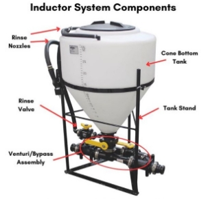
    Disinfecting Scope - Know Before You Go

    No two areas are created equal when it comes to cleaning and disinfecting. Case in point, you don't clean and disinfect an office space in the same way you do a meat packing processing floor. That makes understanding your scope of disinfection all the more important before ever beginning the cleaning process.

    Product Needs

    Pure hard surface disinfectant

    Purehard surface disinfectant; ideal for food processing & food preparation


    For instance, the size of the area you're disinfecting will greatly influence the amount of product needed. Do you need a 5-gallon bucket of disinfectant or a 55-gallon drum? Maybe you need more. This is where foam disinfectants really have the advantage. Their enhanced coverage and prolonged contact time with the applied surface allow less product usage.

    Make note of the GPM flow of your system. If you have a pump that produces 3 GPM of flow attached to a 50 gallon tank, you effectively have 16.5 minutes of continuous application time. Time is money, so how much time will be spent mixing solution is an extremely important thing to remember when disinfecting large areas.

    Disinfectant Systems

    Your style of disinfectant system is something else to keep in mind. Most operations have some level of clean-in-place (CIP) process. However; for a vast majority of the disinfecting process, mobile cleaning units are necessary to leave an area truly decontaminated. Portable disinfectant systems equipped with powerful pumps and spray wands allow an operator to spray disinfectant at a variety of angles, speeds, and tailored quantities. This versatility ensures every hard-to-clean space can be adequately decontaminated.

    Portable Sani-Mister disinfectant unit

    Portable Sani-Mister disinfectant unit


    Ventilation

    Finally, take a minute to evaluate your space's ventilation. Taking the office vs. processing floor scenario, ventilation is likely very different between the two spaces. On the processing floor, the larger area means aerosols and vapors have more room to dissipate or be dispersed by exhaust fans. In the smaller office space, however, chemical fumes become more of a hazard. Respirator masks may be required based upon the chemicals used and/or size and ventilation capabilities of the application area.

    Always be cognizant of how to enter a space for disinfection and understand how your solutions react when in use. Evaluating how to approach an enclosed space for disinfecting and how long someone should be exposed to that environment once they start keeps everyone healthy and safe.

    Safety First: Personal Protective Equipment (PPE) for Disinfecting

    Personal Protective Equipment PPE for Disinfecting


    Regardless of the style of disinfecting you ultimately use, you need to wear personal protective equipment, also known as PPE. This protective equipment ranges from nitrile chemical gloves and safety goggles to full body TYVEK coveralls. These products protect you from spills, splashes, and unexpected contact with the disinfectants which can cause serious chemical burns.

    Reusable Unlined Gloves


    Certain aerosol disinfectants may even require a respirator mask to protect you from harmful chemical vapors. Even if the disinfectant label doesn't list a respirator as required PPE, you may still choose to wear one if working in a small, poorly ventilated space. Each chemical application is different.

    Read your product labels for the proper PPE required to handle specific disinfectants safely. Regularly inspect PPE for wear or damages and replace if needed. Also, ensure your facility has clearly marked eyewash stations and safety showers in case of an emergency. Whether you need gloves, eye protection, or water-resistant clothing, we can help you find the gear you need to be best equipped for the tasks at hand.

    Conclusion

    Proper cleaning and disinfecting procedures will always be a serious focus in the industrial and food processing industries. In fact, one of the most important activities that occurs in any industrial processing facility is their disinfectant regimen. Even so, disinfection practices and policies will continue to change with new health research, product development, and societal perceptions. With that in mind, having a reliable, knowledgeable company you can trust to support you is imperative to your business's success.

    Dultmeier is that company you can trust. We carry an extensive catalog of disinfectants, personal protective gear, and cleaning equipment and supplies from trusted brands like Mosmatic, DEMA, Suttner, General Pump, Hydro Systems, Boss, and others. While we cannot ultimately tell you how to disinfect, we can share with you the many different methods and assist your operation regardless of your choice of application. We'll happily help answer all your questions about various disinfecting types and work to get you the equipment and products you need to ensure your workspaces are cleaner than ever.

    Reach us at dultmeier.com or give us a call at 888-667-5054. Your Experts in Delivering Fluid Handling Solutions - WE KNOW FLOW!

    (0) A New Age of Spraying – How To Size PWM Spray Nozzles

    The commercial spraying industry continues to improve technology. At this point, incremental gains can make a tremendous impact and that incremental gain can be as smaller than a 60 micron droplet. If you have a new spray rig, you're probably not alone. Favorable grain prices paired with government payouts related to COVID-19 have allowed many operations to afford asset upgrades this past year. Maybe that asset upgrade came with Pulse Width Modulation technology? If so, this post is a must read for you prior to sizing your spray nozzles this season.

    Speak at length with anyone involved in the ag sprayer industry about the new advances in sprayer technology, and there is a solid chance you'll hear the phrase "pulse-width modulation" mentioned. Although the technology isn't exactly new, advancements in spray nozzle design and overall efficiency of pulse-width modulation (PWM) spray systems arrive on the market every year, along with a slew of new PWM spray nozzles.

    Following up on our article on sprayer nozzle sizing, we'll focus on explaining how PWM systems work and provide you example-based guidance for how to size a PWM spray nozzle on your own. We'll also explore the benefits of PWM spraying and why it may be time to consider making the switch from a conventional sprayer system to one outfitted with PWM spray nozzles and accessory components. Read on for all the details and be sure to use the table of contents to help you get around.

    Pulse-width Modulation Explained

    Pulse-width modulation was first developed for the agriculture industry in the 1990s by Dr. Ken Giles, a professor of Biological and Agricultural Engineering at the University of California, Davis, and Capstan Ag Systems. For many farmers and agronomists today, however, pulse-width modulation still presents considerable degrees of uncertainty and understanding. So, let's clear up the confusion.

    Pulse-width modulation, in ag-related terms, refers to how liquid flow rates are controlled via an electronic signal and shut off valve. Unlike conventional sprayer booms, a PWM system features nozzle bodies each equipped with an electric solenoid. As this solenoid turns on and off-typically an average of 10 times a second-an intermittent, pulsed spray is created through the nozzle. The proportion of time that the solenoid is open is known as the pulse width or duty cycle. It's this percentage of time the nozzle is open vs. closed that ultimately dictates your rate of application.

    PWM solenoid actuated nozzle body.

    Cross-section illustration of a PWM solenoid-actuated nozzle body.


    Because duty cycle plays such a significant role in determining proper sprayer calibration for PWM operation and PWM nozzle sizing, it's best we dive a little deeper into how this concept works. That way, you will know exactly how to choose the proper size spray nozzle for your specific agricultural operation.

    Duty Cycle - The Driving Force Behind PWM

    One of the limitations of conventional sprayer systems is that nozzle flow varies indirectly with sprayer pressure. As the sprayer speeds up, the system must adjust pressure to also adjust flow rate to deliver the same application rate per acre. Generally, a device called a rate controller automatically recalculates the necessary adjustments for you. So, when the sprayer increases speed, the rate controller causes spray pressure to increase as well until the flow rate sensor shows that the nozzle flow is enough to maintain the target application rate desired.

    There are two related problems with these conventional spray systems. First, pressure must be increased significantly in order to increase flow rate as speed is increased. For instance, nozzle pressure must be doubled for nozzle flow to increase by just 41%. Moreover, pressure must be tripled to increase flow by 73%. Most sprayer pumps cannot achieve this doubling or tripling of their output while increasing flowrate.

    Secondly, sprayer tips are very sensitive to changes in spray pressure. Go too slow and the lower pressure can cause the spray pattern to collapse. The result is poor, inconsistent coverage. Drive too fast, though, and your droplet size becomes finer, creating drift problems. This delicate balance means traditional sprayers must remain within a very specific, narrow speed range, which is not always possible given field conditions or with variable rate applications.
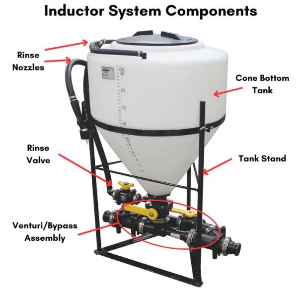
    A key aspect in PWM systems is that spray nozzle output is no longer tied solely to sprayer pressure. Instead, PWM systems focus on duty cycle. Again, duty cycle is the proportion of time that the solenoid is open/on, meaning the percentage of time that your spray nozzles are actually spraying.

    PWM Duty Cycles


    Typical duty cycle ranges are between 20-100%. Although lower duty cycles are possible, they are not recommended since droplet size and spray pattern can become inconsistent.

    During operation, every nozzle can spray at its maximum flow (100% duty cycle) or a fraction of its flow capability. That means a nozzle operating at a 20% duty cycle will deliver about one-fifth of the flow of a spray nozzle spraying 100% of the time. Even so, the pulses occur so quickly that spray pattern and droplet size won't be adversely affected.

    Spray pattern and Droplet size based on duty cycle.


    What does this mean in practice? For one, while duty cycle is still linked to changes in sprayer speed, the spray pressure remains constant. This enables a sprayer operator to make pressure adjustments to maximize coverage or drift control independent of speed and the rate of application. The end result is a spray application that is not only more accurate but also more consistent across diverse field conditions.

    Calculating Duty Cycle

    Duty cycle directly correlates to ground speed. When calculating duty cycle to correctly size your PWM spray nozzles, you want to aim for an average speed around 75% duty cycle. For example, if you figure you'll travel between 10 and 20 MPH while spraying, you'll want to choose your spray nozzle for an average speed of 15 MPH-or 75% of your maximum speed. This gives you plenty of flexibility to adjust the duty cycle up or down if you experience unexpected changes in speed without compromising your droplet size or spray pattern integrity.

    Selecting the Appropriate Spray Nozzle for PWM Systems

    Since the means of controlling nozzle flow rate is different between traditional sprayer setups and those with pulse-modulation, sizing PWM nozzles likewise differs a bit from conventional spray tips. This means that you won't necessarily be able to use traditional flow rate tabulation charts to size your nozzles. No need to fear, though. The PWM spray nozzle sizing process is still easy to understand.

    There are three things to remember when selecting PWM nozzles. For starters, you want to always choose wider angle spray nozzles for pulse-width systems. One of the biggest concerns regarding PWM spraying is the risk of application "skips" as you move through the field. Wider angle nozzles such as 110° flat fans ensure you'll produce enough overlap in your spray coverage to eliminate skipping.

    Additionally, you'll want to avoid using air-inducted spray nozzles for PWM spraying. The introduction of air can compromise the spray pattern and droplet size as the nozzle pulses off and on. As shown in the video below (at 3:18), this deterioration of droplet size is especially obvious upon the valve pulsing off, where residual air causes the application to dribble out from the air inlets-thus rendering the spray nozzle ineffective.

    Now, new advancements have been made regarding air-induced nozzles regarding pulse-width modulation. TeeJet, for example, has several air-induced nozzles that have been approved for PWM use. However, your best bet is still to use non-air-inducted nozzles such as the Turbo TeeJet and Turbo TwinJet. The Greenleaf Soft Drop or Blended Pulse Dual Fan (BPDF) series or Wilger ComboJet series are good options, too.

    Finally, an important point to remember when using PWM systems is that nozzle pressure is different than boom pressure. This is because nozzle pressure/flow is now controlled by the solenoids which are independent of your overall system's pressure reading. As the solenoids turn off and on, a pressure drop needs to be accounted for with higher boom pressure.

    Difference between gauge pressure and nozzle pressure for an 0.8 nozzle.

    Difference between gauge pressure and nozzle pressure for an 0.8 nozzle.


    For example, for a 110-04 spray tip, the average drop is only about 3 PSI. A larger 110-08 tip, however, will push the limits of the solenoid even further, creating a greater decrease in pressure. This can be anywhere from 6 PSI at 30 PSI gauge pressure to 13 PSI at 60 PSI gauge pressure! If the pressure drops too low, the nozzle won't be able to form a uniform spray pattern and droplet size. Therefore, the larger the nozzle orifice, the greater the boom pressure required to compensate.

    PWM charts calculate against this pressure drop and offer speed ranges for operating specific nozzles at a given gauge pressure.

    Sizing PWM Sprayer Nozzles

    Alright, let's size some spray nozzles. A few things you'll need to know ahead of time:

    • Target application rate
    • Typical average speed
    • Desired droplet size

    Using these three components, you'll be able to quickly find the correct spray nozzle size for your PWM application.

    Once you start looking at the charts, just like with conventional spray tips, you want to select a PWM nozzle which falls near the center of the pressure range for your desired droplet size. In most cases, this will be between 40 and 70 PSI for the best pattern and droplet size retention. However, it's difficult to suggest the proper droplet size and nozzle type for every application. As always, check your chemical labels for proper application droplet size before beginning.

    Sizing Greenleaf PWM Nozzles

    For this first example, we're going to find a nozzle within the Greenleaf line of spray nozzles using their PWM tabulation chart. To start, we take our target application rate, let's say 12.5 GPA on 20" spacing, and set our average speed at 15 MPH. Keep in mind we want to maintain a 75% duty cycle through the field. This means we can go as fast as 20 MPH (100%) or as slow as 5 MPH (25%) without exceeding our chosen nozzle's pressure rating or compromising our droplet size or application rate. Our droplet size for this example is Coarse to Very Coarse.

    Finding a nozzle within the Greenleaf line of spray nozzles using their PWM tabulation chart.


    Next, moving down the 75% duty cycle column, we find where our average speed of 15 MPH falls within the 40 to 60 PSI gauge pressure range. Looking left, we see that the best fit is a 0.8 nozzle. We can also readily see that only one nozzle, the BPDF, will provide our desired droplet size.

    Sizing Greenleaf PWM Nozzles


    We could've chosen an 0.7 nozzle, but we're already pushing the pressure limits of that nozzle at our speed. If our average speed was to increase by even one mile to 16 MPH, our droplet size would decrease to Medium. Choosing an 0.8 nozzle still retains our Course-Very Course droplet size even if we were to decrease pressure or speed.

    Sizing TeeJet PWM Nozzles

    TeeJet has a similar approach to sizing PWM nozzles, though their tabulation chart works a bit differently. Instead of providing you with the duty cycle columns, they simply display your minimum/maximum speed range. This means you have to calculate what the 75% duty cycle speed would be on your own. Once you have that however, you can quickly find your ideal spray nozzle.

    Chart highlighting the size of spray nozzle using minimum/maximum speed range


    In the example below, we chose to apply a 15 GPA at 10 MPH with a desired Ultra Coarse or Extremely Course droplet size. We actually have two nozzle options to choose from in this case-the Turbo TeeJet Induction (TTI) and TTI TwinJet (TTI60). Both are again in the 0.8 size.

    15 GPA at 10 MPH with a desired Ultra Coarse or Extremely Course droplet size


    We also have the Air-Inducted Turbo TwinJet (green box) with an XC droplet size if we wanted. However, the larger UC droplet size of the other two nozzles and the fact that they aren't air induction nozzles makes them better options.

    Sizing Wilger PWM Nozzles Using the Wilger Tip Wizard

    Wilger has made selecting their Combo-Jet nozzles for PWM systems even easier via their online Tip Wizard. Here, simply enter your GPA, speed, and target droplet size into the specific fields. You'll also enter nozzle spacing, spray tip angle, and which PWM system you're operating on. Many PWM systems, from Capstan PinPoint to Case AimCommand, Raven Hawkeye to John Deere ExactApply have different actuation speeds. The Tip Wizard will then provide you a list of the best nozzle options given your specifications.

    Wilger's Tip Wizard


    For a complete guide to using Wilger's Tip Wizard and understanding results when sizing nozzles for PWM, click here. They even have a video walkthrough if you prefer that option.

    Advantages of Using Pulse Width Modulation Nozzles

    Although there is no indication that conventional spray nozzles will become obsolete in the near future, the rise of PWM nozzles will undoubtedly continue to assume an increasing share of the industry. And for good reason.

    First, PWM spray nozzles allow you to maintain constant pressure across a wide range of speeds. Having a wider range of travel speeds means that even when speeding up or slowing down through the field, you retain the necessary pressure-and therefore droplet size-to correctly apply your desired chemical rate without sacrificing coverage.

    Drift control is another benefit of using PWM nozzles. While PWM systems do not significantly improve drift control alone, they do make it easier. This is because they offer a wider speed range to work with, meaning you can use larger sprayer nozzles designed for coarser spray patterns. Even if you tweaked your pressure higher or lower, your duty cycle would internally adjust to apply the same application regardless of speed. The larger droplet sizes then allow you optimal drift control.

    Illustration of turn application rates for conventional spray system with rate controller

    Illustration of turn application rates for conventional spray system with rate controller only (left) vs. a PWM system with nozzle-by-nozzle turn compensation capability (right)


    Finally, greater precision. The consistency across numerous speeds means PWM spray nozzles provide incredible application accuracy. Reduction in chemical costs, fewer over- or underapplications, and less drift potential gives PWM operators much more control over their spray operation. Many systems today even have the capability of controlling individual nozzle flows. This nozzle-by-nozzle sectional control enables greater turn compensation and more accurate, site-specific application through the field.

    This feature is especially important when turning around at the end of the row. When turning in a conventional sprayer system, the inner boom nozzles become effectively stationary and substantially over apply chemical. Meanwhile, the outside boom nozzles move faster than the application rate can be accurately applied. PWM systems featuring turn compensation such as Capstan's PinPoint overcome this by individually controlling each nozzle, maximizing efficiency and accuracy.

    Final Thoughts

    As industry leaders continue developing new, better PWM spray equipment systems, understanding PWM technology and how to apply it to your own operation becomes increasingly important. Not unlike sizing conventional sprayer tips, choosing the correct PWM spray nozzle plays an integral role in ensuring the accuracy and efficiency of your sprayer system. After all, your application is only as good as your spray tip.

    For any questions regarding sprayer tip sizing and PWM spray systems, be sure to check us out at dultmeier.com or give us a call at 888-667-5054. We're happy to assist you with whatever questions you may have and provide you the technical expertise and diverse products necessary to get you back in the field. Let us help you find what you're after today so that you get the best sprayer performance possible.

    Your Experts in Delivering Fluid Handling Solutions - WE KNOW FLOW!